English
 Deutsch
 Indonesia


The importance of control valves in industrial automation and maintenance of their positioners.
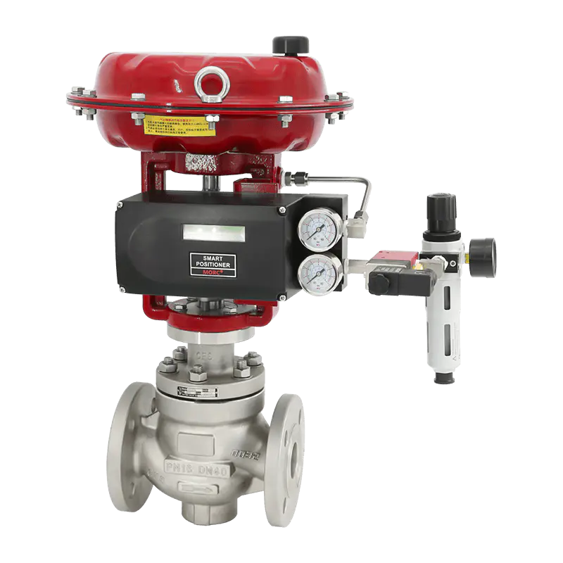
Against the backdrop of accelerating industrial automation, control valves are seeing increasingly widespread application, with their pivotal role in process production becoming increasingly significant. Particularly as the “brain” of pneumatic control valves, valve positioners achieve precise alignment with production process requirements by accurately controlling valve opening. However, in practical applications, valve positioners may encounter various malfunctions. The following provides a professional analysis and compilation of common faults and their solutions.
Fault 1: Valve fails to respond after signal input
1)Air Supply Pressure Verification:
First, ensure the air supply pressure meets the standard requirements specified in the equipment manual.
2)Signal Transmission Path Inspection:
- Use a multimeter to verify the integrity of the 4-20mA signal from the control room to the positioner terminals. If abnormalities are detected, investigate wiring connections.
- If the signal is normal but the positioner fails to respond, conduct further testing of the positioner's internal circuitry.
- For mechanical positioners, pay particular attention to the operational status of the torque motor.
3)Feedback Mechanism Inspection:
Verify that there is no looseness or detachment between the feedback rod and the mounting bracket of the positioner, and perform necessary tightening procedures.
4)Troubleshooting Air Blockage:
Disconnect the air supply line from the positioner's output port and resend the command. If no airflow is detected, the air circuit may be blocked. We recommend returning the unit to the factory for cleaning.
5)Valve Condition Verification:
Carefully inspect the valve itself for any sticking or jamming.
Fault 2: Valve operates slowly
1)Confirming Gas Supply Pressure:
Ensure the gas supply system pressure is sufficient to support valve operation.
2)Air Circuit Leak Inspection:
Thoroughly inspect all air circuit connections for signs of leakage.
3)Valve Impedance Analysis:
Determines whether the valve exhibits sticking or increased frictional resistance.
Fault 3: Valve fails to reach specified position
1)Signal and Air Supply Inspection:
Re-examine the signal transmission process and air supply status.
2)Travel Calibration:
- For mechanical positioners, travel must be adjusted manually;
- Intelligent positioners can optimize relevant parameters through self-tuning functionality.
Fault 4: Valve positioner oscillates near the set point
1)Air Circuit Sealing Performance Test:
Thoroughly inspect the airtightness from the air source outlet of the positioner to the inlet of the actuator.
2)Actuator Status Check:
Eliminate the possibility of internal air leakage within the actuator.
3)Resistance Coefficient and Parameter Fine-Tuning:
- Analyze whether internal friction or other resistance within the valve has increased;
- Utilize the smart positioner to adjust PID parameters or deadband width to reduce unnecessary vibration.
VATTEN offers a variety of locators for selection, including Siemens, YTC, TISSON, and others.