 English
 Deutsch
 Indonesia



Content
- 1 What a Distributed Control System Actually Is
- 2 The Four Layers and What Each One Owns
- 3 DCS, PLC or SCADA: Choosing by Loop Count and Consequence
- 4 The Field Layer Decides Loop Performance
- 5 Final Control Elements: What a DCS Can and Cannot Fix
- 6 Commissioning Practices That Prevent Loop Trouble
- 7 Where a DCS Pays Back
- 8 Frequently Asked Questions
Walk into a control room that has just finished a distributed control system migration and the same picture usually appears: clean trend displays, one historian, one alarm list, and a commissioning engineer quietly admitting that three loops still hunt by two percent. The cabinets are rarely the problem. The field layer is. A DCS is judged by what the transmitter at the tap actually reports, and by how far the control valve really moves when it is told to move.
What a Distributed Control System Actually Is
A distributed control system is a network of process controllers, each owning a defined plant area, that share operator stations, engineering tools and a historian over one communication backbone.
The word distributed refers to control, not to management. Instead of one computer trying to run an entire site, a DCS divides the process into units such as a boiler house, a reactor train or a utility water line, and gives each unit its own controller. If one controller fails, the rest of the plant keeps producing.
That containment explains why continuous plants with hundreds of analog loops standardize on a DCS rather than on one large programmable logic controller rack. Control cycles typically run between 100 ms and one second, and redundancy is normally built into controllers, power supplies and networks.
The single tag database is the real differentiator. In a plant assembled from separate PLCs and a homemade supervisory layer, one measurement often exists three times under three names, with three ranges and three alarm limits. In a DCS the tag is defined once and inherited everywhere.
The Four Layers and What Each One Owns
Whatever brand is painted on the cabinet, a DCS is organized into four layers: field, control, supervisory and enterprise. Knowing which layer owns which decision shortens troubleshooting from days to hours.
| Layer | Typical devices | Signal or protocol | Failure point seen most often |
| Field | Transmitters, positioners, solenoids, limit switches, flow meters | 4-20 mA, HART, RTD and thermocouple | Impulse lines, shield grounding, moisture ingress |
| Control | Controllers, I/O cards, marshalling cabinets, power supplies | Fieldbus, controller backplane | Single power feed, firmware mismatch, dust |
| Supervisory | Operator stations, engineering station, historian, alarm server | Industrial Ethernet, OPC | Flat network design, missing time synchronization |
| Enterprise | MES, ERP and reporting tools | OPC UA, SQL | Uncontrolled writes back toward the control layer |
The pattern is consistent: the cheapest layer causes the longest outages. A transmitter whose impulse line slopes the wrong way will generate more nuisance alarms than any configuration error, and it will keep doing so for fifteen years.
DCS, PLC or SCADA: Choosing by Loop Count and Consequence
Use a PLC for fast machine sequencing, SCADA for assets spread across many locations, and a DCS when one site runs hundreds of continuous, interacting analog loops. The three overlap, and every vendor claims the platform does everything, so decide on engineering reality rather than product category.
PLC
- Tens to a few hundred I/O points
- Scan times of 1 to 20 ms
- Best for machine sequencing and interlocks
DCS
- Hundreds to tens of thousands of points
- Control cycles of 100 ms to one second
- Best for continuous plants with many loops
SCADA
- Many remote sites over telemetry
- Scan times measured in seconds
- Best for water networks and pipelines
The Field Layer Decides Loop Performance
No control algorithm can recover accuracy the field device never delivered. A loop is a chain, and the DCS owns only one link: the controller. Everything else sits in the plant, exposed to heat, vibration, moisture and process fluid.
- Sensor and transmitter selection: range, accuracy class and wetted materials set the achievable loop error before tuning starts.
- Installation quality: impulse line slope, condensate pots, thermowell depth and cable routing.
- Final element sizing: valve Cv, actuator torque, stroke time and fail-safe direction.
- Accessories: positioner, limit switch, solenoid and filter regulator decide how faithfully a signal becomes movement.
- Signal integrity: shielding, grounding and physical separation from variable frequency drive cables.
Transmitters that support HART or another digital protocol deliver more than a single 4-20 mA value. They report sensor drift, electronics temperature and configuration changes, which turns a plant-wide calibration sweep into a targeted task.
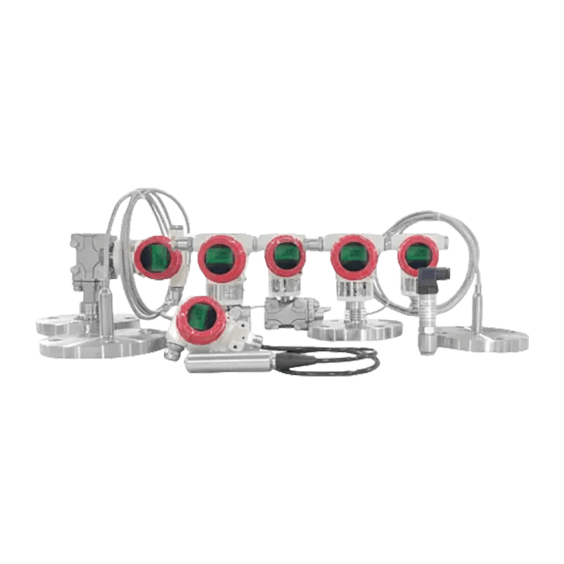 FvLuoky FDP3000 Smart Pressure Transmitter with HART OutputA HART-enabled pressure transmitter for 4-20 mA loops, supporting digital configuration checks with monocrystalline silicon sensing.View Product →
The same logic applies to the final element. A positioner that reports actual travel rather than commanded signal makes stiction visible before it becomes a quality deviation. Suppliers such as Vatten Valve Group assemble valves, actuators, positioners and transmitters into one field set, which matters when a loop has to be repaired once instead of four times.
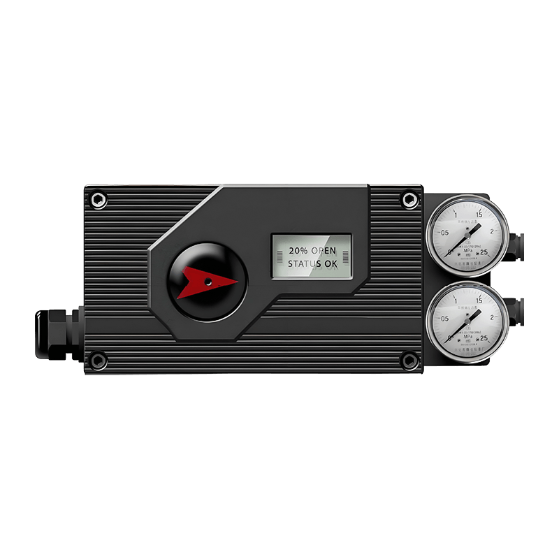 VATTEN Smart Valve Positioner for Precise Valve ControlAn analog 4-20 mA positioner that adjusts actuator air pressure, supporting stable valve positioning in flow and process regulation.View Product →
Final Control Elements: What a DCS Can and Cannot Fix
A control valve is a mechanical device with friction, deadband and hysteresis, and those properties set the ceiling for every tuning exercise that follows.
Pneumatic spring-return actuators remain the default for fail-safe duty because they need no power to reach the safe position. Electric actuators add precise positioning, travel feedback and diagnostics, and they remove instrument air as a failure mode, which suits water, wastewater and remote sites.
Sizing gets less attention than it deserves. An oversized valve runs near the seat, where the installed characteristic is steep and control is poor; an undersized valve cannot pass design flow. Both mistakes survive commissioning because they look acceptable at the design point.
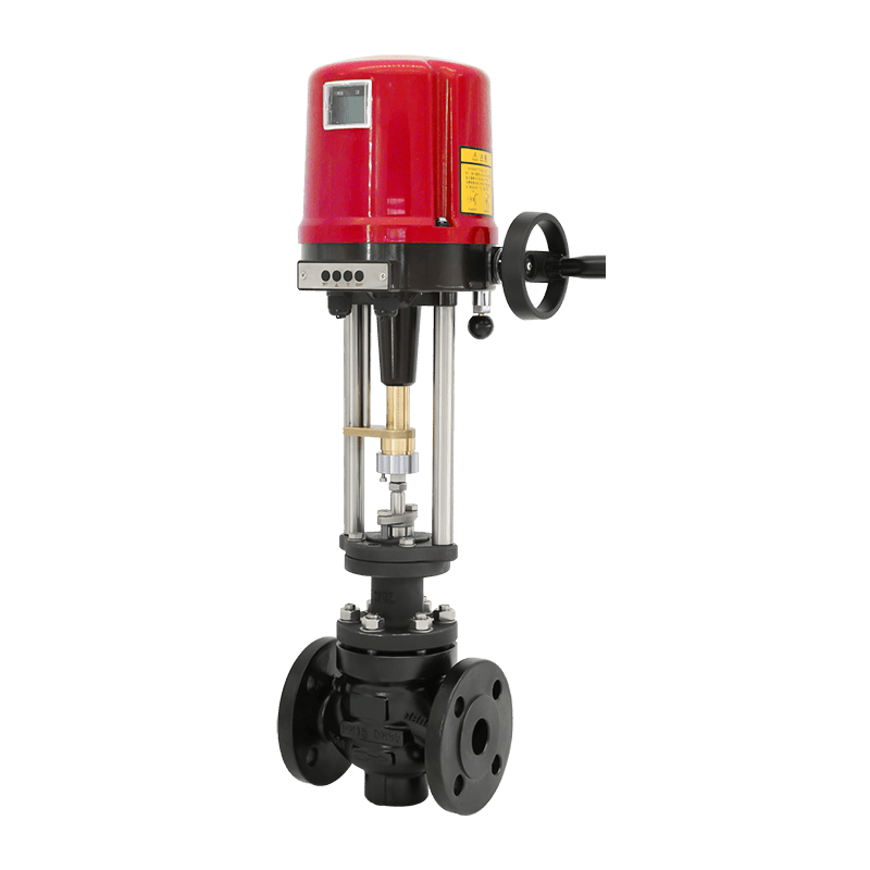 VATTEN Electric Smart Control Valve with Intelligent ActuatorAn electric control valve with 4-20 mA analog control and linear stroke adjustment for accurate regulation in liquid and gas service.View Product →
Commissioning Practices That Prevent Loop Trouble
Most loop faults that appear in the first week of production were visible during commissioning and were signed off anyway. Commissioning a DCS is not mainly a software task; it is an agreement between the field and the control room about what is physically installed.
- Loop check at the marshalling cabinet: inject the signal at the field terminal and confirm the value on the operator screen, not the reverse.
- Stroke test every valve with air and power while the line is still empty, and confirm fail-safe direction.
- Verify positioner feedback: travel span, zero and split range must match the as-built stroke, not the datasheet.
- Tune against the real process, because settings found on water rarely transfer to a viscous slurry.
- Freeze the documentation: updated loop sheets and tag lists stop the next project from repeating the same errors.
Where a DCS Pays Back
The return on a DCS is largest in continuous processes with many interacting loops and expensive downtime.
- Chemicals and petrochemicals, where loops interact and grade changes are frequent
- Power generation, where boiler and turbine control share one operator environment
- Water and wastewater, where distributed sites report to one control room
- Pharmaceuticals, where batch records depend on consistent data
- Battery materials, where slurry and solvent handling punish weak field hardware
These industries share two traits: the process runs continuously, and a shutdown costs more than the control system. Field hardware must survive the same conditions, so materials, sealing class and actuator protection are specified long before the graphics are finished. A recent case study on synchronizing valve supply with a plant expansion shows how much schedule risk sits in the field packages rather than in the control room software.
Frequently Asked Questions
Is a DCS the same as SCADA?
No. SCADA collects and displays data over wide areas, often from remote and unmanned sites, and usually depends on local PLCs or RTUs for control. A DCS performs closed-loop control itself, with the operator interface as one part of the same integrated system.
How many I/O points justify a DCS instead of a PLC?
There is no fixed threshold, but the economics shift when a single site carries several hundred continuous analog loops, when redundancy is mandatory, or when several units must share one alarm philosophy and one historical database. Below that scale, a well-engineered PLC and SCADA combination is usually cheaper.
Can a DCS control valves directly?
It sends a 4-20 mA or digital command to the actuator or positioner and reads back position and status. The physical work of moving the plug or disc is mechanical, so valve sizing, air quality and actuator torque determine the result, not the controller.
A DCS migration is a decade-long commitment. Most of the budget goes into cabinets, licenses and engineering hours, yet most of the operating pain comes back from the field: a drifting transmitter, a sticking valve, instrument air at the wrong dew point. Design the control system as though it were perfect, then spend the field budget as though it were not.