 English
 Deutsch
 Indonesia


Content
- 1 What a Vacuum Relief Valve Does and Why Tanks Fail Without One
- 2 Types of Vacuum Relief Valves and Where Each One Fits
- 3 Sizing a Vacuum Relief Valve: The Numbers That Matter
- 4 Installation and Maintenance That Prevent Field Failures
- 5 Where Vacuum Relief Valves Fit in Industrial Fluid Systems
- 6 Frequently Asked Questions
A 500 cubic meter storage tank drained by a 60 cubic meter per hour transfer pump must admit 60 cubic meters of air per hour while it pumps. When that air cannot get in, the tank does not simply drain more slowly; the roof becomes the weakest structural element in the system.
A vacuum relief valve is the component that decides whether that inward demand is released at a controlled set point or transferred into the shell, the roof, and every fitting welded to them. It is usually the cheapest item on the tank, and its failure tends to produce the most expensive repair.
A flat 5 meter diameter tank roof under only 7 kPa of internal vacuum carries roughly 14 tonnes of downward load, far outside the design envelope of an atmospheric storage roof.
What a Vacuum Relief Valve Does and Why Tanks Fail Without One
A vacuum relief valve is a self-actuated inlet that opens when pressure inside a vessel or piping falls below its vacuum set point and admits air, or an inert gas, until internal pressure returns to that set point.
Definition A vacuum relief valve is a normally closed, weight-loaded or spring-loaded device that protects a closed vessel against external pressure by admitting atmosphere or blanket gas at a defined vacuum set point, typically between 0.5 kPa and 3.5 kPa.
Vessels rarely fail because the pressure difference is large. They fail because atmospheric pressure acts over a very large area. Seven kPa is only about seven percent of one atmosphere, until it is multiplied by the 19.6 square meters of a 5 meter diameter tank roof.
- Top and side panels pulled inward into the classic collapsed roof shape
- Shell distortion that jams internal floats, dip tubes and level instruments
- Gasket extrusion and lining cracks on PTFE lined or glass lined vessels
- Back-siphon of contaminated water or process fluid through an open vent
Four operating events create that vacuum: pump-out faster than the vent can breathe, thermal contraction during cooling or a cold rain shower on a warm tank, steam collapse after a cleaning cycle, and flame arrestors that fouled quietly over several months.
Types of Vacuum Relief Valves and Where Each One Fits
Vacuum protection hardware splits into two families: valves that handle vacuum only, and pressure-vacuum relief valves that handle overpressure and vacuum inside one combined body.
Weight-loaded (pallet)
- Set point comes from pallet mass
- Very few moving parts
- Best below roughly 2 kPa
- Sensitive to mounting angle and build-up
- Common on storage tanks and silos
Spring-loaded
- Set point set by spring compression
- Wider range and higher capacity
- Repeatable after cleaning
- Chosen where a precise set point is required
- Used in vapor recovery and blanketing
The vent path matters as much as the valve body. An open vent discharges to atmosphere, while a pipe-away design routes vapor to a recovery header or scrubber and must be sized for the back pressure that line adds.
Pressure and vacuum protection are normally paired rather than substituted. Overpressure is handled by a spring loaded safety valve sized independently, and the vacuum side is handled by the relief valve, each on its own nozzle and its own set point.
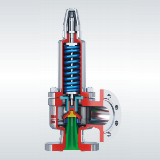 Spring full lift closed safety valveSpring full lift closed safety valve DescriptionView Product →
Never treat the relief connection as a spare port. A valve installed on a nozzle that also carries a dip tube, level probe or sampling line loses both its flow area and its ability to seal.
Sizing a Vacuum Relief Valve: The Numbers That Matter
The controlling number in vacuum relief sizing is the maximum simultaneous liquid outflow, not the connection size of the nozzle it happens to be threaded onto.
| Parameter | Why it matters | Typical practice |
| Vacuum set point | Defines when the valve opens relative to the vessel design external pressure | 0.5 to 3.5 kPa, always below the shell limit |
| Air inlet capacity | Must equal or exceed the worst case simultaneous outflow | Sized at 100 to 120 percent of pump-out rate |
| Connection size | Limits achievable flow once capacity is fixed | Selected after the capacity calculation |
| Temperature and medium | Drives gasket, seat and coating choice | Matched to vapor temperature and chemistry |
| Vent back pressure | Reduces effective capacity in pipe-away installations | Calculated for the full discharge line |
Published air capacities are quoted at standard conditions, so correct them for actual temperature, vapor density and any flame arrestor fitted upstream. On low pressure tanks, venting rules such as API 2000 and ISO 28300 are the usual reference for the required inlet rate.
Installation and Maintenance That Prevent Field Failures
Most vacuum relief valve failures found in service are installation and maintenance problems rather than manufacturing defects.
Mount the valve vertically on the highest point of the vapor space, with a short self-draining connection and no pockets that collect condensate.
Verify the set point on the bench before installation. A pallet that lifts at 2 kPa when the nameplate reads 1 kPa is a handling problem, not a process problem.
Keep the seat, pallet guide and flame arrestor clean. Polymer, crystallized product and ice are the three most common causes of a valve stuck closed.
Re-test after every cleaning cycle, product changeover or shutdown, and record the measured lift pressure against the original value.
- Pallet lifts freely at the marked vacuum set point
- Gasket and seat show no cracking, swelling or extrusion
- Flame arrestor is clean, dry and unobstructed
- Vent path is clear of insulation, bird screens and ice
Where Vacuum Relief Valves Fit in Industrial Fluid Systems
Vacuum relief valves appear wherever a closed vessel can be emptied, cooled or purged faster than it can breathe.
- Atmospheric and low pressure storage tanks in tank farms
- Reactor vessels and mixing tanks emptied from the bottom
- Road tankers, ISO containers and rail cars during unloading
- Hot water and heating circuits during rapid cooldown
- Dry bulk silos, hoppers and pneumatic conveying lines
- Nitrogen blanketed tanks holding solvents or oxidizable products
In blanketed service, the vacuum valve works with the blanketing regulator instead of against it. A nitrogen sealing valve holds a positive pad on the vapor space during pump-out and thermal cycling, which keeps both oxygen ingress and vapor emission inside the limits the process demands.
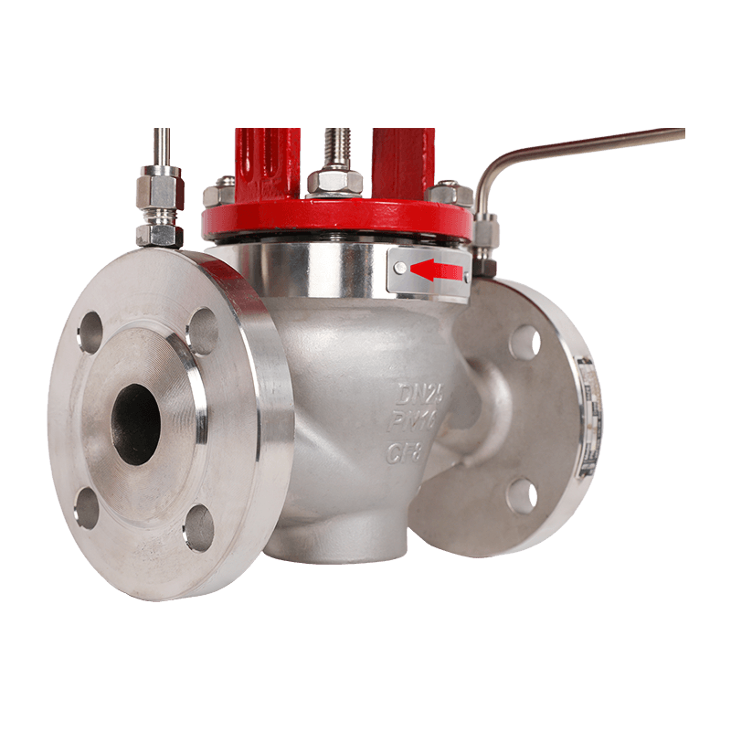 Nitrogen Sealing ValveNitrogen Sealing Valves DescriptionView Product →
On tanks with bottom outlets, the vacuum side is usually specified together with the discharge hardware, because both are sized from the same pump-out rate. The guide to tank bottom discharge valve design covers the sizing side of that pairing in more detail.
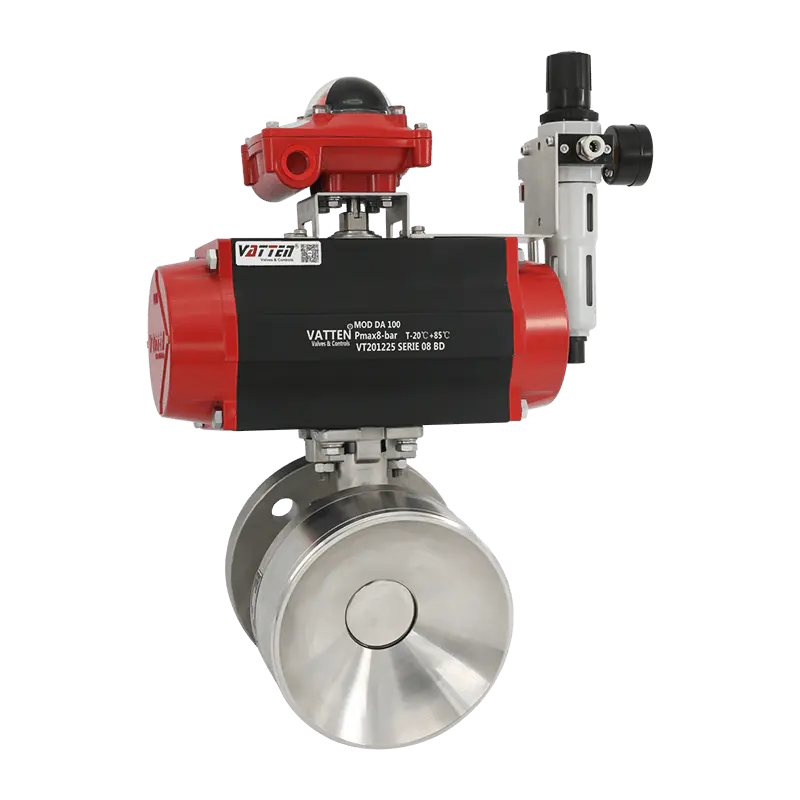 Pneumatic Bottom Ball ValvePneumatic Bottom Ball Valves DescriptionView Product →
If the valve cannot pass the pump-out rate, the tank will find another way to equalize pressure, and that way runs through the roof.
Frequently Asked Questions
These four questions come up in almost every tank protection specification review.
What is the difference between a pressure relief valve and a vacuum relief valve?
A pressure relief valve opens outward and releases fluid to stop overpressure. A vacuum relief valve opens inward and admits air or blanket gas to stop implosion. A pressure-vacuum relief valve combines both functions in one body with two independent set points.
What size vacuum relief valve do I need?
Size by airflow, not by pipe thread. The valve must pass the maximum simultaneous pump-out rate with a margin of roughly 100 to 120 percent, corrected for actual temperature and gas density. Connection size follows from the required capacity.
How often should a vacuum relief valve be inspected?
Inspect every 6 to 12 months and after every product changeover. Confirm that the pallet lifts freely, that the seat and gasket are intact, and that any flame arrestor is clean, dry and unobstructed.
Can a vacuum relief valve be used on water heaters and pipelines?
Yes. On hot water systems they prevent back-siphon and vacuum damage during cooldown. On pipelines they admit air at high points so the line can drain and to prevent column separation during rapid valve closure.
Vacuum protection is a flow requirement, not an accessory. Match air capacity to the worst case outflow, mount the valve where it can breathe, and test it on a schedule.
Relief, blanketing and discharge hardware have to be selected as one system, because they all answer to the same pump curve. Vatten Valve Group supplies that combination for tanks, reactors and transfer lines, and can review vacuum sizing against your actual operating data before a nozzle is welded.