 English
 Deutsch
 Indonesia


Content
- 1 A Miscalculated Torque Value Can Destroy a Valve in Weeks
- 2 How an Electric Butterfly Valve Controls Flow
- 3 Key Types and Where They Fit
- 4 Sizing and Selection: Beyond Just Pipe Diameter
- 5 Electric Actuator Selection: Torque, Speed, and Intelligence
- 6 Material Selection: Body, Disc, and Seat Combinations
- 7 Common Applications Across Industries
- 8 Installation and Maintenance Best Practices
- 9 Comparing Electric Butterfly Valves to Other Quarter-Turn Options
A Miscalculated Torque Value Can Destroy a Valve in Weeks
A poorly sized electric butterfly valve doesn’t just deliver mediocre performance—it can reduce flow efficiency by up to 30% or cause actuator burnout within the first month of operation. This often happens because the valve assembly was chosen from a catalog without verifying actual pressure drop, media characteristics, and required cycle speed.
Electric butterfly valves combine a quarter-turn disc with an electric actuator to control flow in pipelines ranging from 50 mm to over 1,200 mm. They dominate water treatment, HVAC, and general industrial processes because they install easily, require minimal maintenance, and offer precise modulation when paired with the right positioner. The goal here is to cut through catalog confusion and give you selection logic you can use on the next project.
How an Electric Butterfly Valve Controls Flow
A circular disc sits in the center of the pipe. The stem connects the disc to an electric actuator mounted on top of the valve. When the actuator rotates the stem 90 degrees, the disc turns from fully closed to fully open. At intermediate angles, the disc acts as a throttling element, though the flow characteristic is approximately equal percentage—not linear.
The actuator converts electrical energy into mechanical torque through a motor and gear train. A limit switch cuts power when the valve reaches the full-open or full-closed position. For modulating duty, a 4–20 mA positioner continuously adjusts the disc angle. Three-phase actuators typically deliver higher torque in a smaller footprint, while single-phase and DC units serve smaller valves up to DN 150.
The sealing principle distinguishes two broad families: resilient-seated and metal-seated. Resilient seats (EPDM, NBR, PTFE) provide bubble-tight shutoff. Metal seats in high-performance or triple-offset designs handle elevated temperatures and abrasive media where elastomers would fail. Understanding these mechanical facts before selecting an actuator avoids oversizing the motor and wasting budget.
Key Types and Where They Fit
Not all electric butterfly valves share the same body style, connection, or seat design. Choosing the correct type determines installation cost, maintenance accessibility, and long-term sealing performance. The table below summarizes the most common variants.
| Type | Connection | Typical Seat | Common Use |
|---|---|---|---|
| Wafer | Flangeless, clamped between flanges | Resilient (EPDM, NBR) | Water, general HVAC |
| Lug | Threaded inserts for flange bolts | Resilient or PTFE | Dead-end service, frequent maintenance |
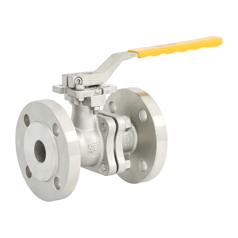
| Flanged | Full flange with bolt holes | Resilient, PTFE, metal | High-pressure, larger diameters |
| Triple Offset | Wafer, lug, or flanged | Metal laminate | High-temperature, cryogenic, zero-leakage |
| High Performance | Typically flanged | PTFE or reinforced PTFE | Chemicals, steam, high-cycle |
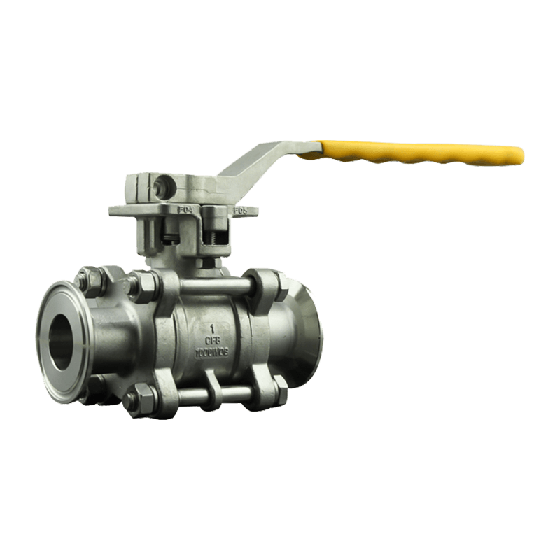
| Sanitary Clamp | Tri-clamp ends | EPDM, PTFE | Food, beverage, pharmaceutical |
| Fluorine Lined | Flanged | PFA or PTFE lining | Severe corrosive chemicals |
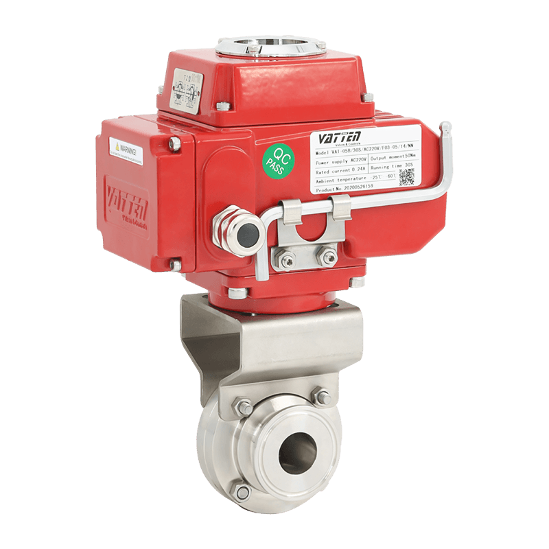
The wafer style remains the most installed electric butterfly valve because it minimizes weight and cost. However, for steam lines or thermal oil applications, a high performance electric butterfly valve with reinforced PTFE seat handles media above 200°C without swelling. In biotech clean-in-place (CIP) systems, an electric sanitary clamp butterfly valve ensures crevice-free sealing and quick disassembly.
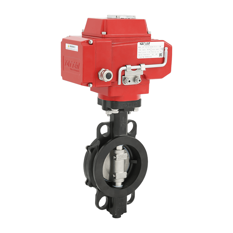
Triple offset designs eliminate rubbing wear between the seat and disc, extending cycle life to hundreds of thousands of operations in demanding refining processes. Flanged models, covered under ASME B16.34 pressure classes, suit larger lines where wafer bodies would require impractical flange support. When dead-end service is required—such as a tank outlet where the downstream side must be isolated—lug style is the safest pick.
Sizing and Selection: Beyond Just Pipe Diameter
Simply matching the valve’s nominal diameter to the pipe is the single largest selection error. Flow coefficient (Cv), pressure drop, velocity limits, and actuator torque must all align. Start with these five checks:
- Calculate the required Cv. Use the valve sizing equation based on actual flow rate and pressure drop. A valve operating between 20° and 70° open provides best controllability.
- Verify line velocity. For liquids, keep velocity under 5 m/s to avoid cavitation and disc flutter. Dry gas service can tolerate higher speeds, but the actuator must overcome dynamic torque.
- Identify shutoff classification. If the process demands zero visible leakage, choose a PTFE-seated or triple offset design rather than standard resilient seats rated for Class VI shutoff per ANSI/FCI 70-2.
- Determine end connection and face-to-face. Wafer and lug valves follow API 609 category A or B face-to-face dimensions. Interchangeability with existing pipe flanges is critical; otherwise, field welding drives up cost.
- Select actuator torque with a 1.5 safety factor. Breakaway torque of the disc in worst-case media (dirty, scaling, or viscous) must be multiplied by at least 1.5 and compared against actuator peak torque charts.
Ignoring media temperature derates both seat material and actuator enclosure. An EPDM seat begins to degrade above 110°C, while a NEMA 4X actuator enclosure keeps moisture out in washdown areas, but fails in high-temperature radiant heat unless an air-purge is added. Always cross-check the combination.
Electric Actuator Selection: Torque, Speed, and Intelligence
The power unit defines how the valve responds to commands. On/off applications need reliable torque delivery and limit switches. Modulating applications need a motor capable of withstanding thousands of starts per hour without overheating. Key actuator parameters include:
- Operating voltage: 24 V DC, 110 V AC, 220 V AC single-phase, or 380–480 V three-phase. Three-phase motors deliver higher torque efficiently and are standard above 200 Nm.
- Duty cycle: Expressed as S2 (short time) or S4 (intermittent). S4-50% means the motor runs 50% of the time with frequent starts. Select accordingly to prevent thermal cutout.
- Control signal: 4–20 mA, 0–10 V, Modbus RTU, or Profibus. A positioner converts the signal into precise disc travel, while a position transmitter feeds back actual position.
- Fail-safe action: Battery backup or spring-return modules drive the valve to a safe position (open or closed) during power loss. This is essential in fire safety or chemical isolation applications.
A modulating electric actuator on a butterfly valve often requires a linkage or direct mount that eliminates backlash. A few degrees of lost motion translate into noticeable flow instability. High-resolution encoders and adaptive control algorithms in modern actuators compensate for gear wear and reduce overshoot.
Material Selection: Body, Disc, and Seat Combinations
Material selection directly impacts corrosion resistance, cleanability, and pressure rating. The body typically is cast iron (GG25), ductile iron (GGG50), carbon steel, or stainless steel (CF8/CF8M). For potable water, ductile iron with NSF-61 certified epoxy coating avoids red rust. For mild chemicals, a stainless steel 316 body with PTFE seat offers broad compatibility.
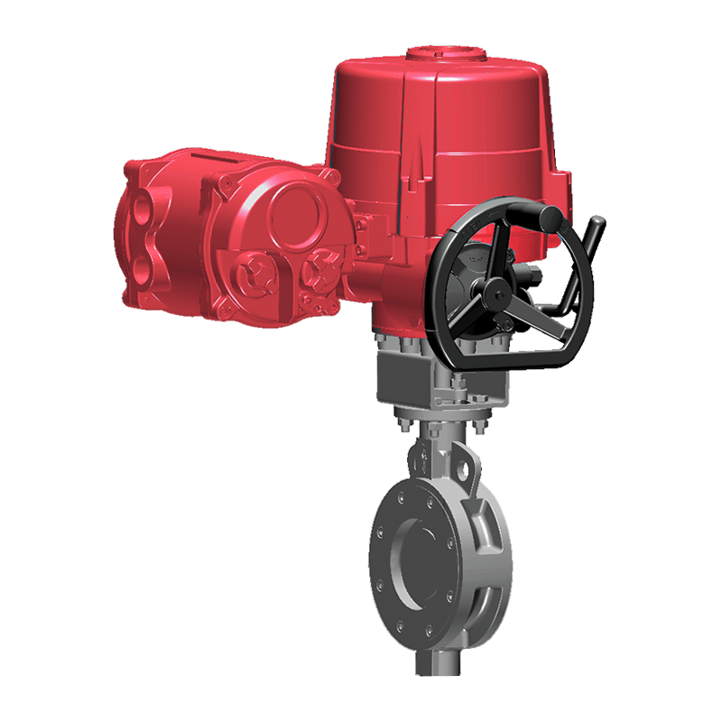
Disc materials range from ductile iron with nickel coating to full stainless steel or Hastelloy in extreme services. Seat choice is what keeps the valve tight. EPDM handles water and dilute acids up to 110°C. NBR works for hydrocarbon-based fluids. PTFE and reinforced PTFE (RTFE) extend the temperature range to 200°C and resist chemical attack. For temperatures to 600°C, a metal-to-metal seal in a triple offset electric butterfly valve is mandatory.
A mistake frequently seen in the field is using an NBR seat with aggressive cooling water containing oil—swelling occurs within weeks, causing disc binding and actuator overload. Matching seat material to the exact chemical concentration and temperature is non-negotiable.
Common Applications Across Industries
Electric butterfly valves appear in systems where pneumatic power is unavailable or where electrical control integrates more cleanly into plant automation. A few high-value examples:
- Municipal water distribution: Large-diameter flanged valves with modulating actuators control flow into reservoirs, often linked to SCADA via 4–20 mA. Low pressure drop across the thin disc profile saves pumping energy.
- HVAC chilled water: Wafer or lug style valves with 0–10 V actuators merge into building management systems, balancing flow through chiller arrays and cooling towers.
- Chemical dosing: PTFE-lined electric butterfly valves with 24 V DC actuators meter aggressive fluids like hydrochloric acid, where bubble-tight shutoff prevents cross-contamination.
- Food & beverage CIP: Sanitary clamp valves with EPDM or PTFE seats meet 3A standards, and the electric actuator eliminates compressed air, simplifying washdown environments.
In applications that mix high temperature and severe chemicals, high-performance electric butterfly valves with stem extensions keep the actuator away from heat, maintaining reliability without complex air lines.
Installation and Maintenance Best Practices
Even the best-specified valve fails early if installed incorrectly. Follow these guidelines to protect the investment:
- Confirm flange alignment. The pipe flanges must be parallel and concentric. Misalignment beyond 1 mm can distort the body and cause seat leakage on resilient-seated valves.
- Keep the disc partially open during welding. If welding is needed on adjacent pipe, leave the disc in a partly open position to prevent heat damage to the seat from slag or spatter.
- Set limit switches precisely. After mounting the actuator, manually jog the valve to the fully closed position and adjust the close limit switch. Then back off mechanically to prevent motor stall. A torque switch serves as secondary protection.
- Exercise infrequently operated valves. Valves that stay in one position for months can develop stiction. A control system programmed to cycle them 5° every 30 days prevents sediment buildup and maintains seat pliability.
- Inspect stem seals annually. The primary stem seal (O-ring or V-ring) wears with modulation. If media begins to leak around the stem, replace the seal before it corrodes the shaft or actuator adapter.
Periodic torque monitoring via actuator diagnostics reveals disc binding or seat wear long before a visible leak occurs. Many intelligent actuators log torque profiles, offering early warning that avoids unplanned downtime.
Comparing Electric Butterfly Valves to Other Quarter-Turn Options
When weighing an electric butterfly valve against an electric ball valve or an electric gate valve, consider the system’s space, pressure drop, and sealing requirements. Butterfly valves occupy roughly 70% less face-to-face space than a flanged ball valve of the same diameter, and they weigh significantly less. That reduces pipe support costs dramatically on large lines.
However, butterfly valves present a disc in the flow path even when fully open, causing a permanent pressure drop. In clean water services, this drop is negligible below 3 m/s. In slurry or high-fiber media, the disc can catch debris and affect closing. For these duties, a full-port electric ball valve eliminates the flow obstruction at a higher price. Electric gate valves, though linear, suit infrequent isolation rather than frequent modulation. The electric butterfly valve remains the superior choice when fast operation, moderate-pressure tight shutoff, and compact automation are required together.