English
 Deutsch
 Indonesia


Content
- 1 The Core Function: Balancing Flow, Not Just Stopping It
- 2 Calibrating the Orifice: Temperature and Viscosity Implications
- 3 Installation Geometry and Turbulence Management
- 4 Selecting the Metering Curve: Linear vs. Equal Percentage
- 5 Optimizing Exhaust Control in Pneumatic Cylinders
- 6 Electrohydraulic Proportional Integration
- 7 Managing Entrained Contamination in High-Cycle Systems
- 8 Sizing Logic for Steam and Compressible Media
- 9 Field Calibration Tactics Without Expensive Flow Meters
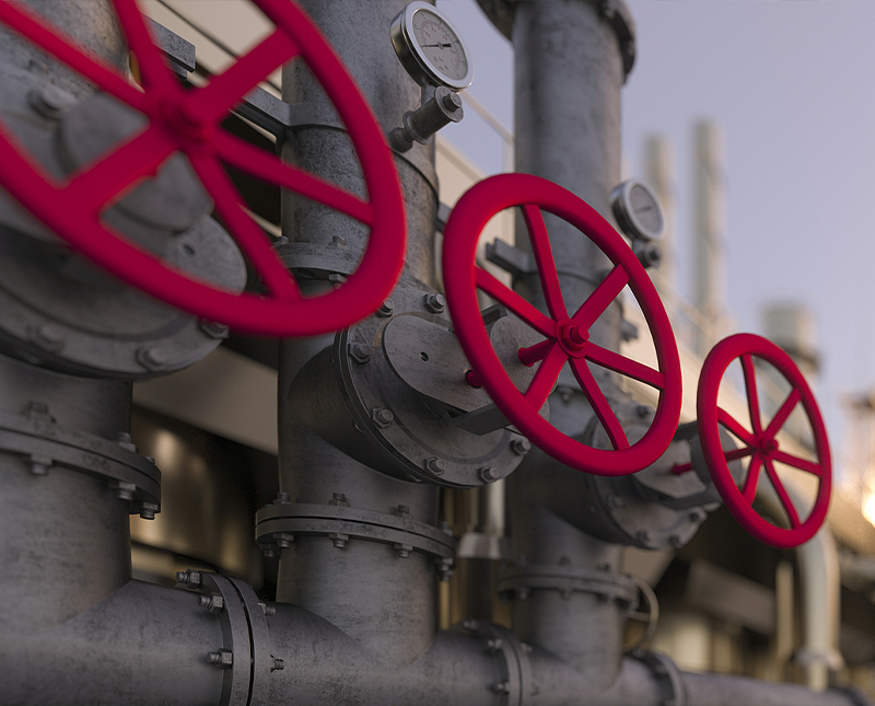
The Core Function: Balancing Flow, Not Just Stopping It
Flow control valves are fundamentally misunderstood if viewed simply as on-off switches. Their primary engineered purpose is the precise regulation of fluid rate—be it liquid or gas—within a dynamic system. A properly specified valve compensates for pressure fluctuations to maintain a stable actuator speed or process volume. Unlike basic ball or gate valves, dedicated flow control designs manage the delicate balance between pressure differential and orifice size. For instance, in a hydraulic press, the valve doesn't just permit oil to move; it dictates the exact velocity of the ram by metering exhaust flow, preventing a destructive slamming effect. This compensation mechanism is critical, especially in systems with variable loads, where maintaining a constant flow despite a shifting pressure drop defines the valve's true utility.
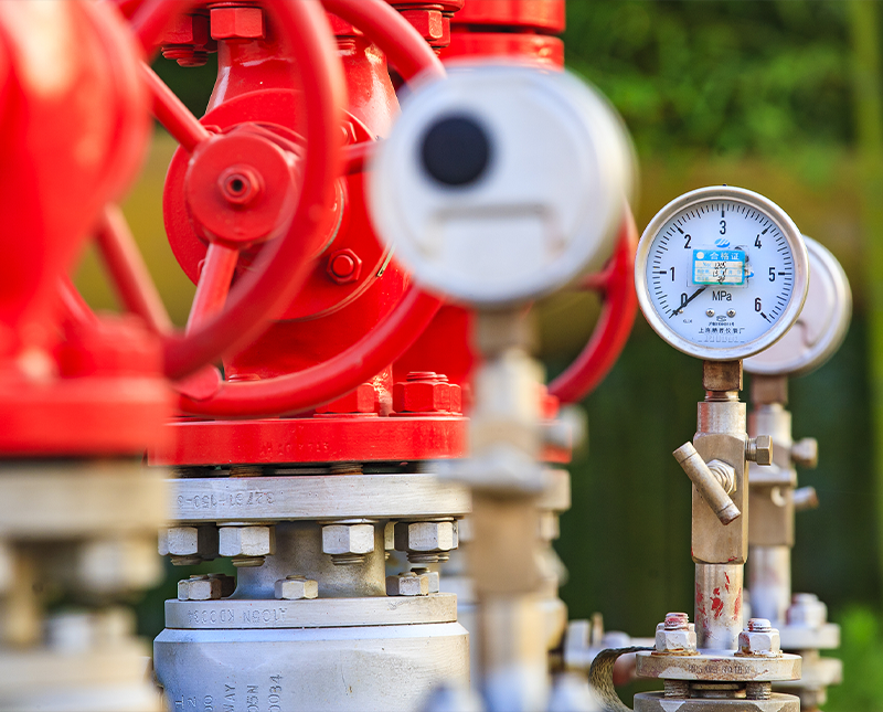
Pressure Compensation Mechanics
The defining feature of an advanced flow control valve is pressure compensation. A standard orifice allows flow to surge when downstream resistance drops, but a compensated valve integrates a hydrostat within the body. This internal regulator automatically adjusts the orifice opening in response to upstream or downstream pressure changes. The result is a steady flow rate within plus or minus three to five percent accuracy, even when system pressure fluctuates by hundreds of PSI. This precision is non-negotiable in applications like chemical dosing pumps or aerial lift platforms, where speed consistency directly correlates to safety and product quality. Without this mechanism, a heavy load could cause a cylinder to drift erratically, turning a controlled movement into a safety hazard.
Calibrating the Orifice: Temperature and Viscosity Implications
Material selection and design geometry directly determine how a valve handles thermal shifts. Hydraulic oil viscosity can swing dramatically between a cold startup at 40 degrees Fahrenheit and operational peaks near 180 degrees Fahrenheit. A sharp-edged orifice design offers a distinct advantage here; its flow coefficient remains relatively stable across viscosity changes because the flow separation point is fixed, making it less viscosity-dependent than a long, drilled passage. This is vital for mobile equipment operating in extreme weather. In contrast, a needle valve offers fine low-flow adjustment, but its annular geometry makes it more sensitive to viscosity. Real-world data shows that a sharp-edged design might exhibit only a 10 percent flow deviation over a 100-degree range, where a needle type could deviate by 25 percent or more, risking actuator lag in cold environments.
Viscosity-Independent Design Choices
When a process spans broad temperature bands, two valve categories excel: rotary eccentric valves and pressure-compensated bypass units that thermally bleed excess flow. The rotary option creates a turbulent path where fluid shear is constant, effectively decoupling flow from viscosity. This prevents a heat exchanger’s cooling water control loop from suffering hunting oscillations as seasons change. Selecting these designs removes the need for constant manual re-tuning and protects against the cavitation damage that arises when thin, hot fluid vaporizes across a restriction point. The physical geometry serves as a built-in safeguard against thermal flux.
Installation Geometry and Turbulence Management
Severe performance degradation often traces back not to the valve itself, but to the piping layout immediately surrounding it. Flow control devices require a fully developed, symmetrical velocity profile to function accurately. A common and destructive installation error places the valve directly downstream of a 90-degree elbow or a partially open gate valve. This creates a spiraling flow stream and velocity stratification, rendering the valve's internal pressure reading inaccurate. Engineering guidelines typically mandate a straight run of pipe equaling 10 to 15 diameters upstream and 5 diameters downstream. Ignoring this turns a high-precision compensated valve into a guessing device. For example, in a natural gas metering run, disturbing the flow profile has been shown to cause a measurement error exceeding two percent—an unacceptable loss in custody transfer billing.
Avoiding Cavitation Through Backpressure
When a liquid flows through a restriction, local velocity skyrockets and static pressure plummets. If pressure drops below the vapor pressure, vapor bubbles form and violently implode downstream—a condition called cavitation that erodes even hardened steel internals within weeks. To prevent this, the valve must be installed with a fixed throttle or backpressure module located directly after the metering orifice. This increases the downstream backpressure, the valve must be positioned at the lowest practical thermal point to keep the fluid's vapor pressure margin as wide as possible, effectively using gravity and system architecture to suppress flashing before it can begin.
Selecting the Metering Curve: Linear vs. Equal Percentage
Valve performance hinges on the relationship between stem travel and flow capacity, known as the inherent flow characteristic. Selecting the wrong curve can make a process loop nearly impossible to calibrate. The table below dissects the two primary metering logics based on common system behaviors and pressure distribution.
| Feature | Linear Curve Design | Equal Percentage Design |
|---|---|---|
| Flow to Stroke Ratio | Directly proportional | Exponential increase |
| Best Application | Systems with over 70% pressure drop across the valve | Systems with less than 30% pressure drop at the valve |
| Low-End Controllability | Can be overly sensitive near the closed position | Precise fine-tuning at initial opening stages |
| Physical Plug Shape | Cylindrical or flat-faced | Logarithmic contour with a fluted or sculpted skirt |
The equal percentage curve solves a fundamental fluid dynamics problem: as the valve opens and flow increases, the distribution line friction loss escalates, reducing the actual pressure differential across the valve. The exponential opening counteracts this loss of driving force, creating an installed characteristic that behaves linearly to the control system. In a chilled water plant with extensive piping, using a linear valve would result in a loop that barely reacts for the first 30 percent of the stroke, then slams wide open at the end, forcing the actuator to hunt endlessly.
Optimizing Exhaust Control in Pneumatic Cylinders
In pneumatic systems, controlling the actuator exhaust inherently delivers smoother motion than throttling the intake supply. When a meter-out circuit restricts air leaving the cylinder, pressure builds on the dead side of the piston, creating a resisting pneumatic cushion. This counters the natural stick-slip phenomenon where static friction suddenly drops to kinetic friction, which causes erratic chattering during slow movements. By using a reverse-flow check bypass within the flow control valve, free air rushes in through a one-way check, but exhaust is forced through a fine needle restriction. Implemented correctly, this transforms jerky breakaway torque into a steady, controlled extension, critical for tasks like inserting electronic components onto fragile circuit boards where impact shock is intolerable.
The Meter-Out Advantage for Vertical Loads
Safety circuits handling suspended loads must use a meter-out configuration without exception. If flow is controlled on the inlet side of a vertical cylinder, gravity can pull the piston down faster than the incoming air can fill the cap end, creating a runaway condition and a low-pressure void. Controlling the outgoing air locks the descending mass against a captive air spring, preventing a free-fall collapse in the event of a supply line rupture. Integration with a quick-exhaust valve at the inlet can further reduce backpressure during the working stroke, splitting the circuit to gain efficiency on the push while retaining absolute safety on the retract—a vital combination for automotive lift systems.
Electrohydraulic Proportional Integration
The boundary between manual flow setting and closed-loop automation blurs with proportional solenoid control. These valves move a spool incrementally based on a variable electrical signal, typically a 0 to 10-volt or 4 to 20-milliamp input. Unlike servo valves with extreme filtration requirements, proportional valves tolerate standard ISO 4406 contamination levels while still achieving hysteresis levels under four percent. This makes them the practical bridge between basic manual hydraulics and full digital motion control. Applied in a plastic injection molding machine, the ramping of the electrical signal directly correlates to the injection speed profile, allowing the machine to fill the cavity slowly at first to prevent air entrapment, then accelerate to full volume, a critical sequence impossible with a manual twist knob.
Closed-Loop Feedback via LVDT
For high-precision tensile testing machines where load frame stiffness varies, simple proportional open-loop control may drift. The solution integrates a Linear Variable Differential Transformer (LVDT) within the valve body. This sensor measures exact spool position down to the micron and sends a feedback voltage to the driver amplifier. The card instantly compares commanded position against actual presence, correcting the spool position thousands of times per second, effectively nullifying flow force interference that tries to slam the spool shut. The precision improvement is measurable; a standard open-loop proportional valve might hold a 10-gallon-per-minute setting within a 0.8-gallon window, while the closed-loop variant shrinks that window to a steady-state deviation under 0.05 gallons, an essential margin for catalytic chemical reactions where mix ratios dictate molecular integrity.
Managing Entrained Contamination in High-Cycle Systems
Fluid cleanliness directly dictates the life cycle of a flow control valve, with particulate erosion and silting defining two distinct failure mechanisms. Modern mobile hydraulic systems frequently cycle flow valves at 50 hertz or more, creating intense localized velocity jets that grind micron-sized debris against metering edges. The symptom, known as erosive washout, permanently alters the designed orifice shape and erodes the sharp, square edge that defines viscosity insensitivity. A study of failed directional and flow control cartridges reveals that over 70 percent of premature failures stem from a breached contamination profile, not mechanical fatigue. The countermeasure involves aggressive kidney-loop filtration, targeting an ISO 16/14/11 rating specifically to protect thin-edge metal seats from becoming rounded, leaky thresholds.
Silt-Lock Prevention in Static Standby
A distinct contamination threat arises not from flowing fluid, but from static pressure locking. Valves sitting in a standby position for weeks allow ultra-fine silt, smaller than 5 microns, to migrate into the radial clearance between the spool and bore. Over time, this sludge polymerizes, creating a breakaway stiction force that can overwhelm the spring centering force, causing the valve to fail on the first attempted shift. This "silting" causes erratic deadband spikes. The preventative approach uses a dither signal—a low-amplitude, high-frequency AC overlay on the solenoid current—causing the spool to vibrate imperceptibly without moving the main flow path. This micro-motion prevents the static adherence of polarized particles and ensures the valve breaks free at the exact commanded input threshold.
Sizing Logic for Steam and Compressible Media
Applying liquid-sizing formulas to gas or steam creates a critical safety valve undersizing condition. Choked flow, a state where the downstream velocity reaches sonic limits and mass flow ceases to increase regardless of dropping outlet pressure, dominates compressible media calculations. The valve's flow coefficient alone is insufficient; the pressure differential ratio determines if the flow is subsonic or choked. A typical globe-style flow control valve handling 150-pound saturated steam must account for the inlet density and expansion factor. If the absolute outlet pressure drops below roughly 45 to 50 percent of the absolute inlet pressure, the flow becomes choked. Ignoring this ceiling leads to dangerously low flow calculations, undersized steam heat exchangers, and production bottlenecks where heating duty cannot physically be met through the contracted vena contracta gap.
Aerodynamic Noise Attenuation
High-pressure drop gas flows generate sound pressure levels exceeding 110 dBA when left unchecked, a direct byproduct of turbulent shear and shockwave formation at the throttling point. This occupational hazard is mitigated not by thicker pipe insulation, but by source control within the valve trim. Multi-stage cage trims subdivide the total pressure loss into a series of smaller drops, preventing the formation of a single, deafening shock cell. A single-seated valve on a 600 PSI natural gas line might howl at 115 dBA, while a multi-path, tortuous-trim replacement can attenuate the noise to a safe 85 dBA threshold. This staged throttling preserves the mass flow capability while shattering the coherent noise-generating turbulence into smaller, destructive interference waves in the high-frequency spectrum.
Field Calibration Tactics Without Expensive Flow Meters
A precision flow meter is ideal, but a maintenance crew can calibrate a valve to near-factory accuracy using cylinder timing and a stopwatch. For a hydraulic cylinder, the internal diameter is a known constant. By stroking the actuator fully and timing the duration, the flow rate is derived directly from the volume divided by time, using the formula (Area x Stroke Length / Time). This volumetric method inherently accounts for any subtle internal bypass leakage that a static test would miss. For instance, if a 4-inch bore cylinder with a 20-inch stroke retracts in exactly 8 seconds under controlled flow, the effective flow rate is precisely calculable without cutting the line. This technique provides an immediate pass/fail metric for valve performance against its original test specs on the production floor.
Delta-P Measurement Across the Valve
To separate a faulty valve from a dying pump, the pressure drop across the valve must be isolated. A single pressure gauge placed directly upstream and another tapped directly downstream in the actuator line provides the truth. Under a steady load, a widening delta-P indicates an internal spring fatigue or seat wear, where the valve orifice is opening wider than commanded to try and compensate. If the delta-P drops to near zero even when the valve is commanded at 25 percent open, the metering element is likely blown out or jammed by debris. This differential diagnosis avoids the costly mistake of replacing the entire power unit when the root cause is a five-dollar seal failure inside the cartridge, easily solved with a simple rebuild kit and a cleaning bath.