 English
 Deutsch
 Indonesia


Content
- 1 How a Pneumatic Flow Control Valve Works
- 2 Meter-In vs. Meter-Out: Which Configuration Fits Your Circuit?
- 3 Selecting the Right Pneumatic Flow Control Valve
- 4 Vatten Pneumatic Flow Control Valves for Continuous Industrial Service
- 5 Installation and Maintenance Practices That Keep Speed Control Reliable
- 6 The Small Valve with a Large Effect
Picture a pneumatic cylinder on a packaging line extending with enough force to dent the carton it is supposed to push. The technician reaches for a small fitting with a knurled adjustment knob, turns it down a quarter of the way, and the problem disappears. That fitting is a pneumatic flow control valve, one of the simplest and most cost-effective components in an industrial air system.
Here is the bottom line: a pneumatic flow control valve limits the flow rate of compressed air in one direction, which controls the speed of the actuator it feeds. It does not stop flow completely, and it does not regulate pressure. What it does, at very low cost, is give you precise command of how fast a cylinder extends, retracts, or moves a load.
How a Pneumatic Flow Control Valve Works
A pneumatic flow control valve combines two functions in one body. A needle valve provides an adjustable restriction that throttles the airflow, while an integrated check valve allows free flow in the opposite direction. The combination produces one-way speed regulation: flow is metered through the needle in the controlled direction, then bypasses the restriction completely when the actuator exhausts or retracts.
The relationship between the needle opening and the resulting flow follows the basic orifice equation: flow increases with the square root of the pressure drop across the valve and with the effective area of the opening. Turning the needle clockwise reduces the orifice area and lowers the flow; turning it counterclockwise opens the orifice and raises the flow. Because the check valve opens fully in the reverse direction, the uncontrolled side of the circuit sees almost no added restriction.
Orifices in pneumatic flow controls come in two broad types:
- Fixed orifices have a constant drilled area and are used when the speed setting never changes.
- Variable orifices use a needle-and-seat arrangement in which the area is adjusted by turning the valve stem.
This one-way behavior has a practical consequence: a single flow control valve slows only one stroke direction of a cylinder. If both extension and retraction must be controlled, install one valve at each actuator port, oriented so the needle throttles the flow in the direction you want to slow.
Meter-In vs. Meter-Out: Which Configuration Fits Your Circuit?
The first real engineering decision is where to install the flow control valve relative to the actuator. Meter-in control throttles the supply air entering the cylinder. Meter-out control throttles the exhaust air leaving it. The choice changes how the actuator behaves under load, and it is not merely a matter of mounting convenience.
| Characteristic | Meter-In Control | Meter-Out Control |
|---|---|---|
| Valve location | Supply line, between the directional valve and the actuator | Exhaust line, between the actuator and the directional valve |
| What is throttled | Incoming compressed air | Outgoing exhaust air |
| Best suited for | Single-acting spring-return cylinders; low-speed circuits; air knives and blow-off nozzles | Double-acting cylinders; rodless cylinders; strokes longer than 3 inches (75 mm); higher-speed systems |
| Key advantage | Direct control of fill air; simple setup | Back pressure in the cylinder dampens load changes; smoother motion |
| Common drawback | Restricted supply can reduce cylinder force and cause chatter or stick-slip motion | Requires careful sizing; oversized valves make fine adjustment difficult |
Meter-out control is the preferred choice for most double-acting cylinders in industrial service. The back pressure created by throttling the exhaust keeps the piston under tension in both directions, which smooths out load fluctuations and prevents the abrupt, jerky motion that appears when a heavy load starts moving. Meter-in control has a narrower field of use: it suits light single-acting cylinders and applications such as air knives, where you deliberately want to limit the volume of air being blown downstream.
The one problem to watch for with meter-in control is stick-slip. When supply air is heavily restricted, the pressure building behind the piston can be insufficient to overcome seal friction smoothly. The cylinder then moves in small jumps rather than at a constant speed. If you see this behavior, move the valve to the exhaust port and use meter-out instead.
Selecting the Right Pneumatic Flow Control Valve
A flow control valve that is too small will starve the actuator under peak demand. One that is too large will make speed adjustment coarse and frustrating. These selection criteria keep you in the right operating window.
Flow Capacity (Cv)
The flow coefficient indicates how much air the valve can pass at a given pressure differential. Calculate the actuator's air consumption per stroke, then choose a valve whose Cv is in the same order of magnitude as the requirement. If the actuator needs high cycle rates, select a valve with a slightly higher Cv and use the adjustment knob to bring the speed down. Sizing tight and running the needle wide open leaves no room for tuning.
Pressure and Temperature Limits
Standard pneumatic flow control valves are typically rated for supply pressures up to about 10 bar (145 psi). Temperature is the boundary where buyers often get into trouble. Cold outdoor plants, low-temperature processes, and refrigerated environments make standard elastomers stiff and brittle, which shows up as creeping leaks around the adjustment stem. For those conditions, use a low-temperature-rated valve with suitable seal materials rather than pushing a standard unit beyond its specification.
Port Size, Connection Type, and Body Material
The valve must match the rest of the circuit. Threaded ports, push-in fittings, and flanged connections each have their place, and adding adapters introduces pressure losses and potential leak points. Body material matters too: anodized aluminum serves ordinary factory air well; stainless steel is the right choice for washdown areas, chemical atmospheres, and food-processing environments where corrosion resistance is non-negotiable.
Needle Resolution and Control Characteristic
Not all flow control valves are built the same. A coarse needle works fine for general cylinder speed, but if your process depends on repeatable small changes in speed, such as dosing strokes, filling nozzles, or press feeds, a precision flow control valve with a finely tapered needle gives you the resolution to make small adjustments without the valve going from too slow to too fast in a fraction of a turn.
If you are replacing a valve in an existing system and the symptoms point to the valve rather than to the cylinder, the guide to flow control valve selection offers a practical reference on drive types, sizing, and failure modes.
Vatten Pneumatic Flow Control Valves for Continuous Industrial Service
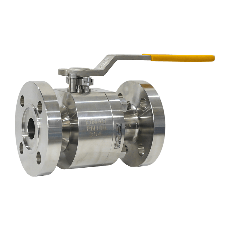
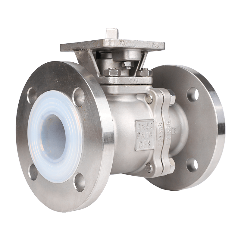
Vatten's pneumatic flow control valves are built for continuous industrial duty, with body materials, seal compounds, and needle geometry selected for real process conditions. The range covers three functional variants that handle the majority of installations found in chemical plants, water treatment facilities, and general production machinery.
Precise speed control for quality-sensitive processes
When actuator speed directly affects product quality, in dosing, filling, or press strokes, the pneumatic precise flow control valve delivers the fine needle resolution needed to make small, repeatable adjustments without hunting or overshoot.
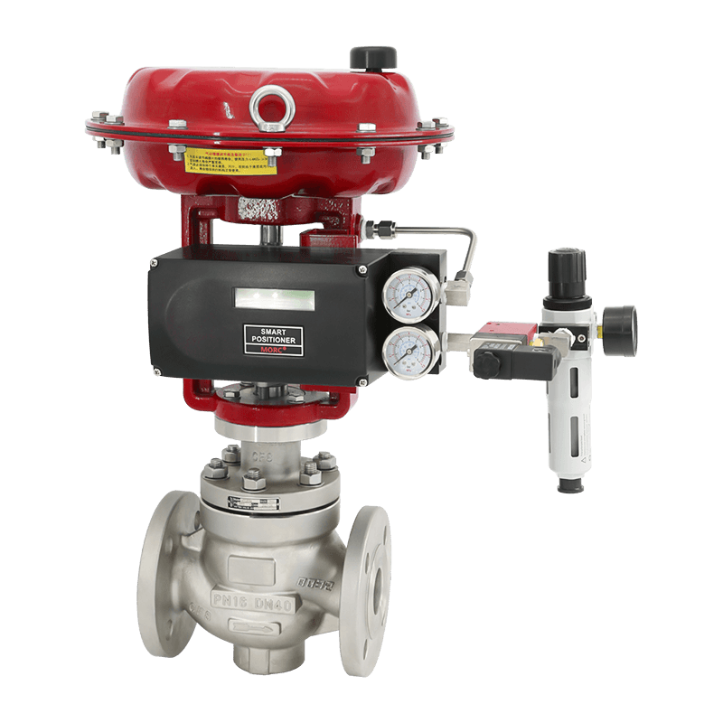 Pneumatic Flow Control ValveThe VATTEN pneumatic...View Product →
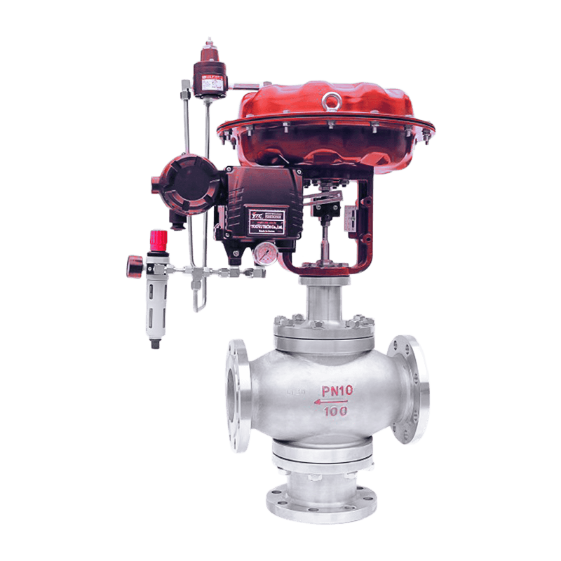
Three-way flow control for compact circuits
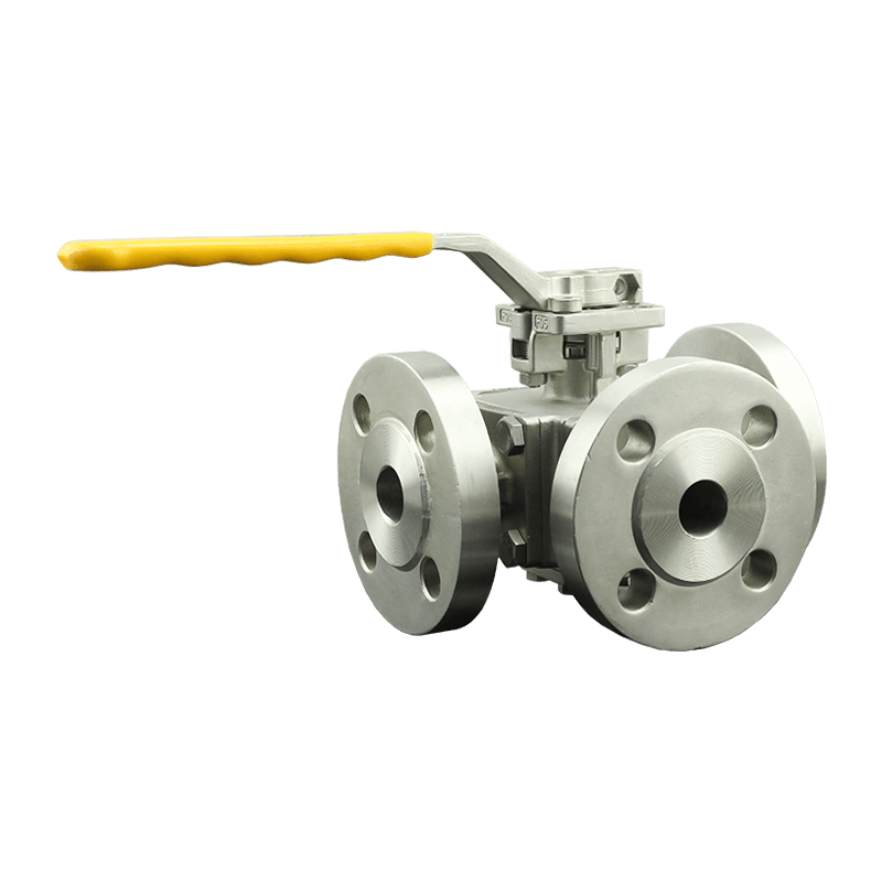
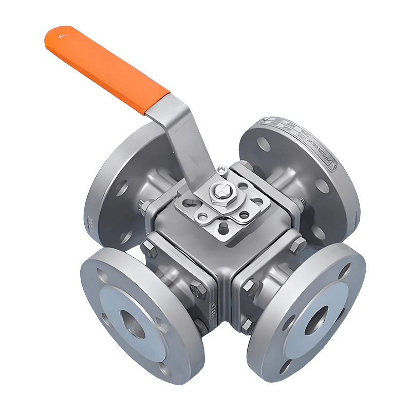
Some circuits need supply and exhaust flow control in a single body to simplify the piping and reduce component count. The pneumatic three-way flow control valve integrates both flow paths into one compact component, which shortens installation time and reduces the number of potential leak points.
 Pneumatic Flow Control ValveThe VATTEN pneumatic...View Product →
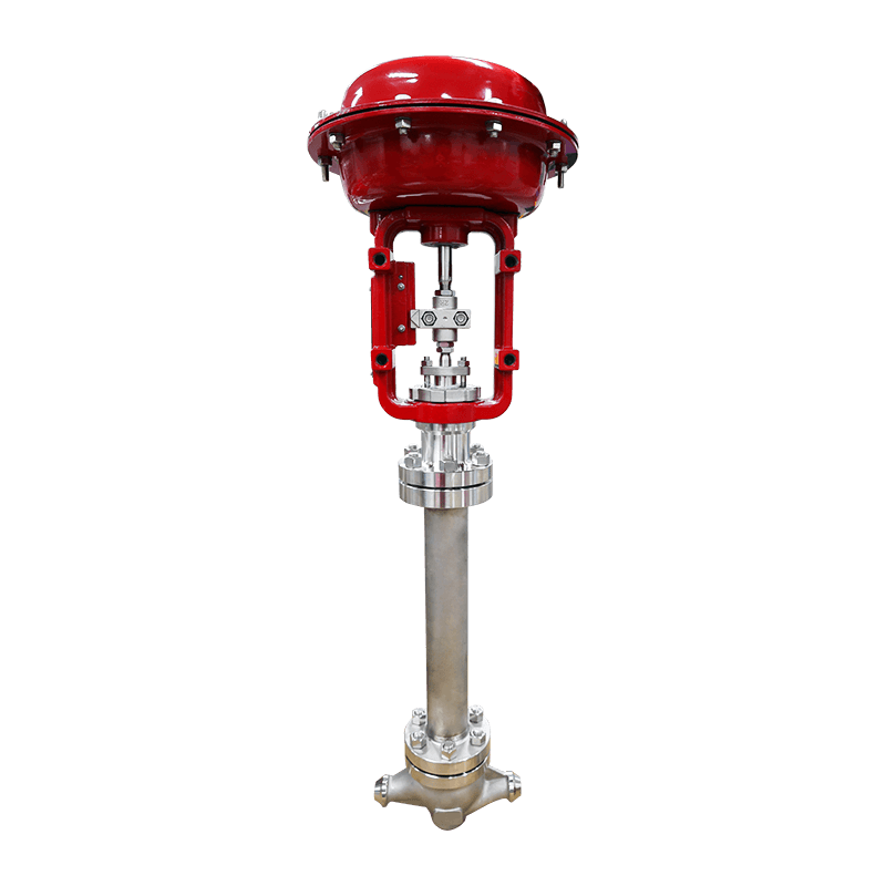
Low-temperature flow control for cold environments
Outdoor air systems, cold-storage plants, and winterized process skids place special demands on valve seals. The pneumatic low-temperature flow control valve uses low-temperature-compatible elastomers to keep the adjustment stem sealed and the needle action stable when standard valves start to stiffen and leak.
 Pneumatic Flow Control ValveThe VATTEN pneumatic...View Product →
Installation and Maintenance Practices That Keep Speed Control Reliable
A good valve still performs poorly if it is installed in the wrong position or neglected for years. These are the practices that keep pneumatic speed control stable over decades of service.
Place the filter-regulator upstream
Dirt and water are the main enemies of a needle valve. A filter-regulator installed upstream of the flow control protects the needle edge, keeps the adjustment characteristic consistent, and prevents the sticking that develops when compressor oil and condensate dry onto the stem.
Mount the flow control valve close to the actuator
For meter-out control in particular, the distance between the valve and the cylinder port matters. Trapped air volume between the valve and the actuator acts as a cushion, making the speed setting less responsive and less repeatable. Mount the valve directly at the cylinder port, or as close to it as the piping allows.
Record settings before any maintenance
When a cylinder is replaced or a fitting is changed, flow settings are frequently lost. Mark the needle position or record the number of turns from fully closed before disconnecting anything. The maintenance checklist for flow control valves covers the routine inspection steps, including cleaning the needle, checking for thread wear, and verifying that the check valve seats properly.
The Small Valve with a Large Effect
Pneumatic flow control valves rarely appear in plant drawings as headline components, but they determine whether a cylinder moves smoothly or slams, whether a cycle time is repeatable or drifts, and whether an actuator lasts five years or five months. Understanding the working principle, choosing meter-out or meter-in deliberately, and selecting a valve with the right Cv, temperature rating, and needle resolution will save far more time than the few minutes it takes to size the valve properly.
For industrial users, the practical benefit of a well-chosen flow control valve is simple: predictable actuator speed, fewer damaged products, less mechanical wear, and a machine that behaves the same at the start of the shift as it does eight hours later.