English
 Deutsch
 Indonesia


Content
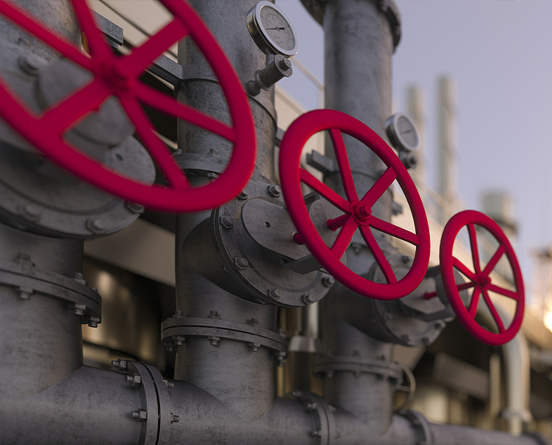
What Are Reaction Vessel Valves and Why Do They Matter
Reaction vessel valves are specialized flow-control components installed on reactors, autoclaves, pressure vessels, and mixing tanks to regulate the entry and exit of process media — including liquids, gases, slurries, and steam — under controlled temperature and pressure conditions. They are not general-purpose industrial valves. Their materials, sealing geometry, actuation mechanisms, and pressure ratings are all engineered specifically for the demanding chemical, thermal, and mechanical environment found inside and around reaction vessels.
The correct valve selection directly affects reaction yield, product purity, operator safety, and equipment service life. A valve that leaks, corrodes prematurely, or throttles inconsistently can introduce contaminants, cause uncontrolled pressure excursions, or trigger costly unplanned shutdowns. In high-throughput chemical, pharmaceutical, or petrochemical operations, even a brief process interruption translates to significant financial loss.
Common Types of Reaction Vessel Valves
Different reaction processes require different valve configurations. The most widely used types include:
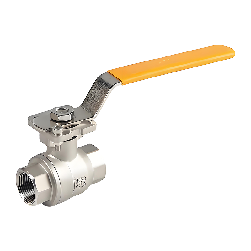
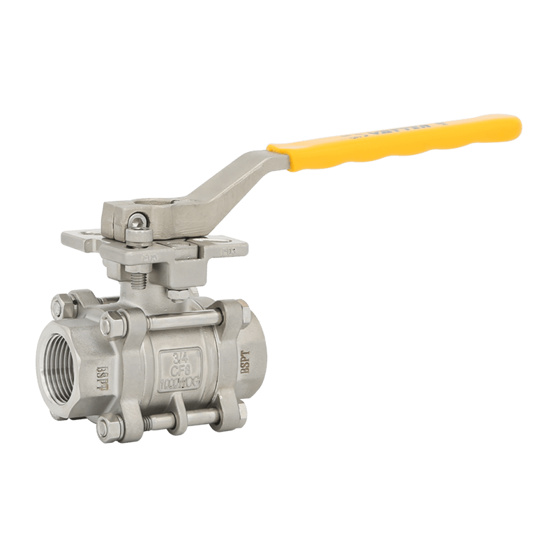
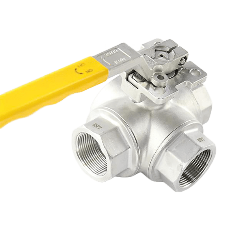
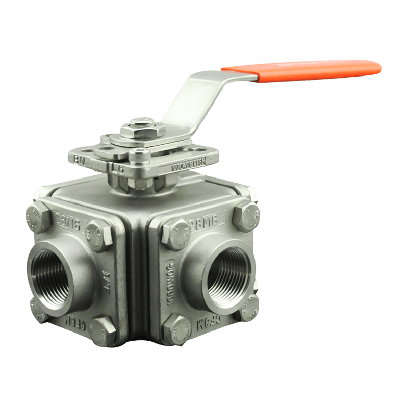
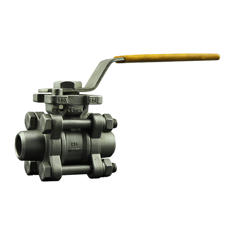
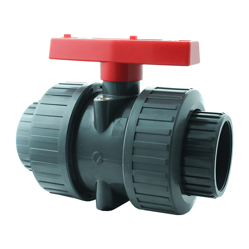
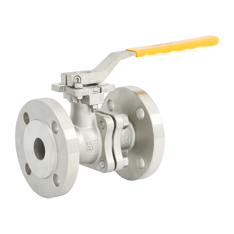
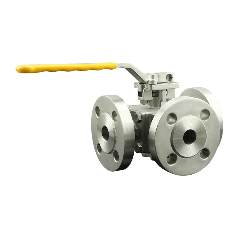
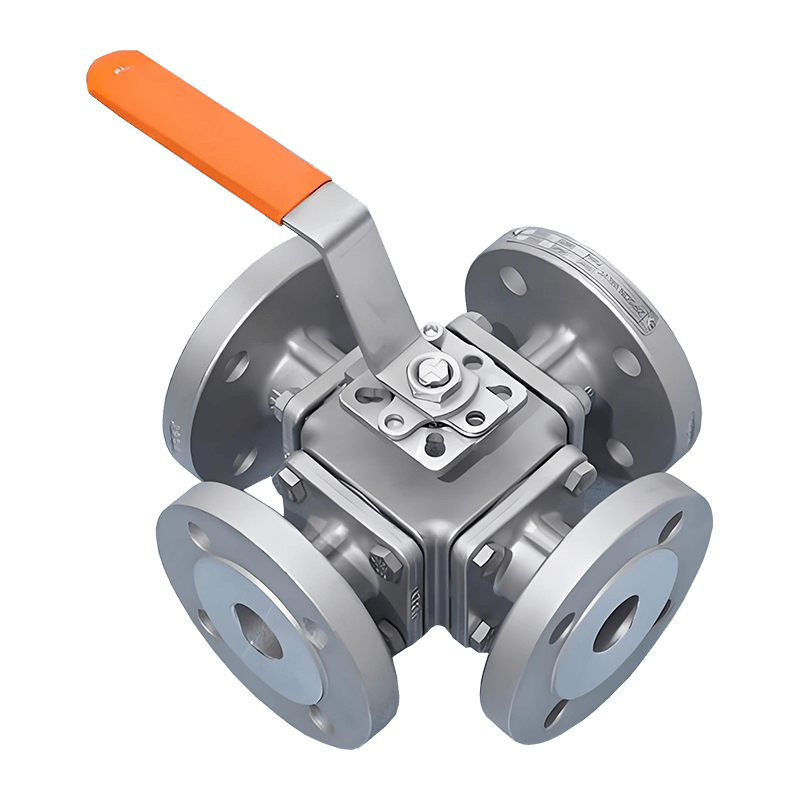
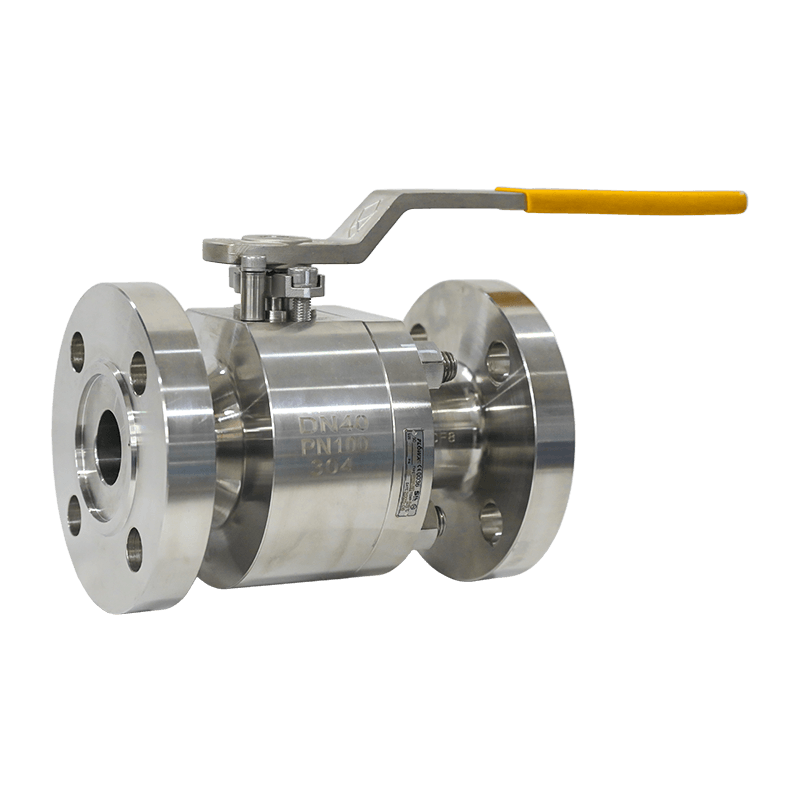
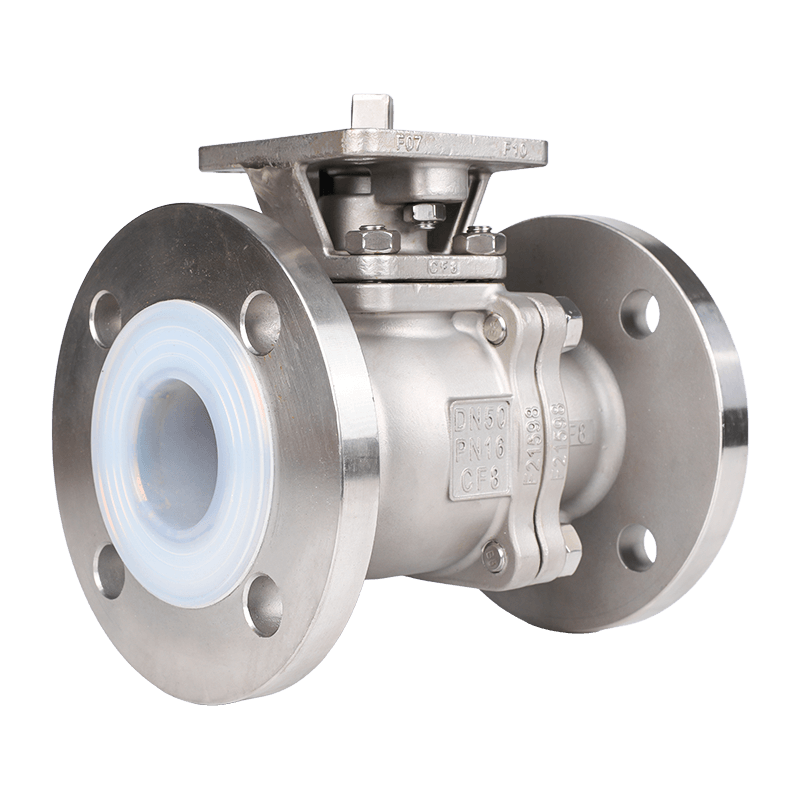
- Ball Valves — Preferred for quick isolation duty. Quarter-turn operation provides a tight shutoff, making them suitable for both feed-inlet and product-outlet positions on batch reactors. Full-bore designs minimize pressure drop during charging and discharge.
- Globe Valves — Used where precise flow throttling is required, such as controlling reactant addition rates or regulating cooling-water flow to jacket circuits. The parabolic plug design offers fine control but generates higher pressure drop than ball or gate configurations.
- Gate Valves — Suited for low-frequency isolation of large-diameter process lines. They provide minimal resistance to flow when fully open but are not recommended for throttling due to vibration and disc erosion.
- Diaphragm Valves — Widely adopted in pharmaceutical and fine-chemical reactors. The flexible diaphragm completely isolates the actuator and body cavity from process fluid, eliminating dead legs and simplifying clean-in-place (CIP) and steam-in-place (SIP) procedures.
- Needle Valves — Used for small-diameter instrumentation connections, sampling ports, and precise gas dosing into the vessel. Their tapered stem design delivers fine metering capability.
- Safety Relief Valves — Mandatory on pressure vessels under most international codes (ASME, PED, GB 150). They open automatically when vessel pressure exceeds the set point, protecting the vessel shell, nozzles, and downstream equipment from overpressure damage.
Key Selection Criteria
Selecting the right reaction vessel valve requires evaluating multiple parameters simultaneously. Treating any single factor in isolation leads to premature failure or unsafe operation.
Pressure and Temperature Rating
Valves must be rated for the maximum allowable working pressure (MAWP) and the full temperature range of the process, including start-up, steady-state, and emergency conditions. Ratings are typically expressed as pressure-temperature (P-T) classes per ASME B16.34 or equivalent standards. For high-pressure hydrogenation reactors operating above 20 MPa, forged body construction with extended bonnet designs is standard.
Material Compatibility
The valve body, trim, and sealing elements must resist corrosion, erosion, and swelling when exposed to process chemicals. Common material choices include:
| Process Environment | Recommended Body Material | Seal / Seat Material |
|---|---|---|
| Aqueous acids (dilute) | 316L Stainless Steel | PTFE / EPDM |
| Concentrated sulfuric acid | Hastelloy C-276 | PTFE / Graphite |
| Chlorinated solvents | Duplex Stainless / Hastelloy | PTFE / FKM |
| High-temperature steam | Carbon Steel / Alloy Steel | Graphite / Metal-seated |
| Pharmaceutical / biotech | 316L SS (electropolished) | PTFE / Silicone (USP Class VI) |
Leakage Class and Fugitive Emission Control
Environmental regulations in most jurisdictions require strict control of fugitive emissions from valve stems and body joints. Valves used on reaction vessels handling volatile organic compounds (VOCs) or toxic gases must meet ISO 15848-1 or equivalent fugitive emission standards. Low-emission packing sets — typically multi-layer PTFE or flexible graphite — are specified, and live-loaded packing glands are used to maintain sealing force through thermal cycling.
Actuation and Automation Compatibility
Modern reaction vessel skids increasingly rely on automated process control. Valves must accept pneumatic, electric, or hydraulic actuators and integrate with positioners, solenoids, and limit switches compatible with 4–20 mA, HART, PROFIBUS, or Foundation Fieldbus protocols. For safety-instrumented functions (SIL-rated loops), partial-stroke testing capability is required to verify actuator operability without taking the valve offline.
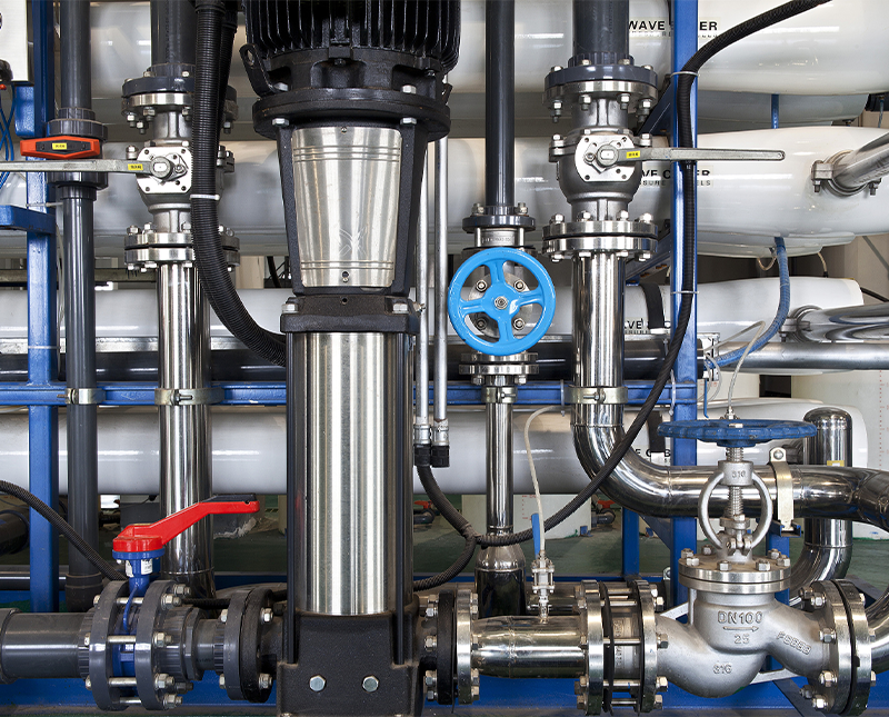
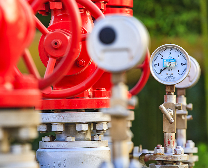
Installation, Maintenance, and Inspection Best Practices
Even correctly specified valves fail prematurely if installed or maintained improperly. The following practices significantly extend service life and maintain process integrity:
- Proper orientation — Many valve types, including globe and check valves, have a required flow direction marked on the body. Reversed installation causes seat erosion, water hammer, or failure to close under differential pressure.
- Flange alignment — Forcing misaligned flanges together during installation introduces bending stress on the valve body, which can cause gasket blowout or body cracking during pressure excursions. Flanges should be aligned before bolting.
- Packing inspection intervals — Stem packing should be inspected for leakage at every planned outage and replaced according to the manufacturer's schedule or after any event involving thermal shock. Re-torquing the packing gland nut without replacing worn packing is a temporary measure only.
- Seat and disc inspection — Valves on abrasive slurry or catalyst-laden streams should undergo internal inspection at least once per operating cycle. Wire-draw erosion on globe valve plugs and butterfly disc edges is a leading cause of unplanned leakage.
- Safety relief valve testing — Pressure relief devices must be bench-tested and re-certified at intervals defined by local pressure vessel codes — typically every 2 to 5 years depending on service severity. In-service pop testing is not a substitute for full bench calibration.
- Torque documentation — All bolted connections on valve flanges and gland followers should be torqued to specification with calibrated tools, and the values recorded. This creates a baseline for future re-torque checks and supports pressure vessel inspection records.
Industry Standards and Certification Requirements
Reaction vessel valves used in regulated industries must comply with a range of national and international standards. Understanding which codes apply to a given installation is essential before procurement:
- ASME B16.34 — Covers pressure-temperature ratings, materials, dimensions, and testing requirements for valves in pressure piping systems. Widely referenced in North American chemical and petrochemical plants.
- API 6D / 608 — Applies to pipeline ball and plug valves, including those used on reactor feed and product transfer lines in oil and gas applications.
- EN 13709 / EN 1983 — European standards for globe, gate, and ball valves in industrial applications, aligned with the Pressure Equipment Directive (PED 2014/68/EU).
- ISO 15848-1 / ISO 15848-2 — Defines measurement, test, and qualification procedures for fugitive emission performance of industrial valves.
- ASME VIII Div. 1 / Div. 2 — Although these codes govern vessel design rather than valves directly, they define the nozzle ratings and test pressures that vessel-mounted valves must accommodate.
- FDA / GMP regulations — For pharmaceutical and biotech reactors, valves must be manufactured from materials listed in FDA 21 CFR and must support sanitary design principles including drainability, surface finish (Ra ≤ 0.8 µm), and crevice-free internal geometry.
Mill test reports (MTRs) for valve body and trim materials, hydrostatic shell and seat test certificates, and fugitive emission test reports should all be requested from the manufacturer and retained in the equipment file for the operational life of the vessel.
Emerging Trends in Reaction Vessel Valve Technology
The design and application of reaction vessel valves continue to evolve alongside broader advances in process automation, digitalization, and sustainability-driven engineering:
- Smart valve positioners with diagnostics — Modern digital positioners continuously monitor stem travel, actuator air consumption, and friction signature. Deviations from baseline indicate developing seat wear, packing degradation, or actuator failure — allowing predictive maintenance scheduling rather than time-based replacement.
- Additive-manufactured trim components — 3D printing in corrosion-resistant alloys such as Inconel 625 is being used to produce complex internal trim geometries — multi-stage pressure-reducing cages, anti-cavitation discs — that are difficult or impossible to machine conventionally. Lead times for critical spares are also reduced significantly.
- Hydrogen service optimization — As green hydrogen production scales up, demand is growing for valves qualified per ASME B31.12 and NACE MR0175 for high-pressure hydrogen service. Special attention is paid to hydrogen embrittlement resistance in body materials and the selection of compatible elastomeric seals.
- Wireless position monitoring — Battery-powered wireless limit switches using WirelessHART or ISA100.11a protocols eliminate instrument cabling in explosion-hazardous zones and simplify installation on retrofit projects.
- Low-emission and zero-emission designs — Stricter VOC emission regulations in the EU (Industrial Emissions Directive) and the US (EPA Method 21) are driving adoption of bellows-sealed globe valves and cryogenic extended-stem designs that achieve leak rates below 10 ppm by volume.