 English
 Deutsch
 Indonesia






Content
- 1 What a Belleville Spring Actually Is
- 2 Reading the Load-Deflection Curve Before You Choose an h/t Ratio
- 3 Stacking: How Series and Parallel Configurations Change Load and Travel
- 4 Where Belleville Washers Do Real Work in Valve and Piping Hardware
- 5 Material, Finish and Tolerance Details That Decide Service Life
- 6 A Practical Selection Sequence
- 7 Frequently Asked Questions
A steam-jacketed transfer line cycles from ambient to 160 C four times a day. The gland bolts were torqued to specification at commissioning, yet by the end of the first week the packing is weeping. Nothing has come loose. The joint has simply shortened by a few hundredths of a millimeter as gasket and packing relax under heat, and a flat washer cannot follow that movement. A Belleville spring can.
That mix of short stroke and high force is why coned-disc washers turn up on valve bonnets, flange bolts, seat assemblies and relief trim far more often than most maintenance files record. Getting them right comes down to a handful of dimensions and two stacking decisions, and most field failures trace back to one of those being skipped.
What a Belleville Spring Actually Is
A Belleville spring is a washer-shaped compression spring formed as a shallow cone frustum. Loaded axially, the cone flattens: deflection per disc is usually well under a millimeter, while the force it carries is large for the height it occupies. Most industrial specifications follow DIN 2093, which fixes the dimensional series, the thickness tolerance groups and the material condition.
Four values describe the part: outer diameter, inner diameter, material thickness t, and cone height h. Everything else, including the shape of the load curve and the fatigue behavior, follows from them.
Definition: a Belleville spring, also called a coned-disc spring or disc washer, stores elastic energy by flattening a truncated cone. The ratio h/t, cone height divided by material thickness, sets its load-deflection behavior almost on its own.
| Characteristic | Belleville disc spring | Helical compression spring | Flat washer |
| Force in a short stack | High, often kilonewtons per disc | Moderate, requires free length | None |
| Travel per element | Small, typically 0.2 to 1.0 mm | Large, tens of millimeters | Zero |
| Typical failure mode | Fatigue crack, load loss after relaxation | Buckling, permanent set | Loosening, galling |
| Typical valve duty | Gland live loading, seat energizing, bolted joints | Safety valve set pressure, actuator return | Load spreading under bolt heads |
Reading the Load-Deflection Curve Before You Choose an h/t Ratio
The h/t ratio decides the shape of the load-deflection curve, and therefore the job the spring can do.
At h/t near 0.4 the curve is close to a straight line: doubling the deflection roughly doubles the force. That makes sizing arithmetic simple and suits bolted joints where the working travel is small and known in advance.
At h/t near 0.75 the curve flattens through the middle of its travel. Force changes very little across a deflection band that can be several tenths of a millimeter wide, which is exactly what a live-loaded gland wants: the packing relaxes, the disc unloads slightly, and the stress on the packing stays inside its sealing window instead of collapsing.
Above roughly 1.3 the curve turns over and the disc enters negative stiffness. That behavior is real and useful in over-center mechanisms, but it is risky under a bolt: a disc that snaps through can invert and lose preload in a single thermal excursion. When a maintenance team reports that a stack went flat for no visible reason, check the h/t before blaming the torque procedure.
Stacking: How Series and Parallel Configurations Change Load and Travel
Parallel stacking multiplies force and series stacking multiplies travel, and no stack does both at once without paying for it in height.
Nested in the same direction, n discs behave as one stiffer element: force is n times a single disc while travel stays the same. Alternated face to back, the same n discs travel n times as far but carry only the force of one disc. Combined groups, two parallel sets placed in series for example, multiply both values, at the cost of a taller pocket and more friction interfaces.
Parallel stack
- Force multiplied by the number of discs
- Travel equal to one disc
- Useful for high preload in a shallow pocket
- Friction rises quickly with count
Series stack
- Travel multiplied by the number of discs
- Force equal to one disc
- Useful for thermal movement and relaxation
- Softer rate, longer installed height
Friction is the quiet variable. Each disc-to-disc interface loses roughly 2 to 5 percent of nominal force between the loading and unloading stroke, so a ten-disc stack can show noticeable hysteresis and a dry stack can read well below the catalog curve. Lubricated stacks tighten that scatter, though the lubricant has to be compatible with the process fluid if the spring sits inside the wetted boundary.
Where Belleville Washers Do Real Work in Valve and Piping Hardware
In valve and piping assemblies, Belleville springs appear in three places: bolted joints that heat cycle, packing glands that must hold constant stress, and seat components that need a light, continuous push.
- Gland and bonnet live loading. A short stack under each gland nut keeps packing stress inside a narrow band as the valve heats and cools. Two to four discs in series usually covers the travel on a steam valve.
- Flange bolted joints. Thermal expansion mismatch between carbon steel pipe and stainless studs is a classic loosening mechanism, and a disc stack compensates without needing a longer stud.
- Seat energization. In ball and butterfly valves, a light disc or wave spring presses the seat against the closure at low differential pressure, then process pressure takes over the sealing load.
- Actuator and bearing preload. Quarter-turn gearboxes and electric actuators use small stacks to remove axial play from the drive train.
- Relief trim and pilot stages. Set-pressure stability depends on spring rate staying constant, and some pilot designs use disc stacks where a helical spring would stand too tall.
The failure pattern that shows up most often in high-temperature ball valves is a seat that seals cold and weeps hot. The seat insert grows, the spring beneath it has to absorb the movement, and an undersized or relaxed spring loses contact pressure exactly when the process reaches temperature. A valve built for that duty should specify seat spring material and available travel rather than leaving it to a generic part.
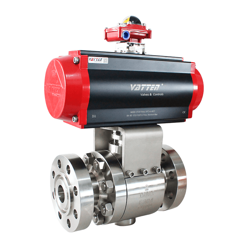 VATTEN Pneumatic High-Temperature Ball ValveHigh-temperature pneumatic ball valve with extended bracket and heat dissipation, relevant when seat spring material and travel must suit thermal movement.View Product →
The same reasoning applies to metal-seated ball valves in abrasive service, where the seat spring has to survive thermal movement and particle ingress at the same time. Our own note on metal-seated ball valves in extreme operating conditions walks through the load path in more detail.
On the relief side, the spring is the calibration element. A spring-loaded safety valve holds its set pressure only as long as the spring rate stays stable, so the spring housing, its guides and any auxiliary disc elements deserve the same scrutiny as the seat and disc.
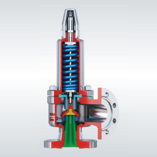 Spring Full Lift Closed Safety ValveSpring-loaded safety valve for overpressure protection, with A42Y-C and A42Y-P/R service limits and PN/DN dimensional tables for selection.View Product →
A practical rule from field work: if the joint moves more than 0.1 mm between cold and hot, or the bolt relaxes more than 5 percent in the first week, a plain washer is the wrong part and a short disc stack will usually fix it without redesigning the stud.
Material, Finish and Tolerance Details That Decide Service Life
Material grade, edge condition and preset treatment decide whether a disc survives a million cycles or cracks at ten thousand, and they matter more than the catalog load rating.
| Material | Temperature guidance | Corrosion resistance | Typical use |
| 50CrV4 or 51CrV4 spring steel | Up to about 250 C with derating | Low, needs plating | General industrial bolting and glands |
| 301 stainless | Up to about 200 C | Moderate | Water, food and light chemical duty |
| 17-7PH precipitation hardening stainless | Up to about 350 C | Good | High fatigue cycles, cleaner service |
| Inconel X-750 | Up to about 600 C | High | Steam, exhaust and hot valve trim |
Four process details carry most of the remaining risk:
- Edge rounding, which removes the sharp corner where fatigue cracks normally start.
- Shot peening, which puts the surface into compression and lifts fatigue life noticeably on cycling parts.
- Presetting to solid height, which removes residual stress and stabilizes the cone height before the part ships.
- Surface treatment, whether phosphating, zinc flake or PTFE, chosen for friction control as much as for corrosion.
Preset is not optional in cycling service. A disc that has been compressed to solid height once will hold its cone height far better than one that has not, and skipping the step usually appears as several percent of load loss within the first hundred cycles, long before any fatigue crack is visible.
A Practical Selection Sequence
Work from the load the joint must keep, not from the nearest catalog page.
- Define the load band. State the minimum stress the joint needs to seal and the maximum the hardware can take, then size to the middle of that window.
- Measure the movement. Thermal expansion, gasket relaxation and creep add up to the travel the spring must absorb. If the number is under 0.2 mm, a single disc is usually enough.
- Pick the disc and the ratio. Choose h/t near 0.4 for a predictable rate, or near 0.75 when constant force across travel matters more than stiffness.
- Decide the stack. Series for travel, parallel for force, and combined groups only when the pocket height allows it.
- Check stress and environment. Confirm the calculated stress sits below the fatigue limit for the material at operating temperature, and that plating or lubricant survives the process fluid.
Frequently Asked Questions
Are Belleville washers and disc springs the same thing?
Yes. Belleville washer, coned-disc spring and disc spring all describe the same truncated-cone part, and the German standard DIN 2093 uses the term Tellerfeder. Naming varies by region and by supplier catalog, but dimensions and load behavior follow the same rules.
Can stacking raise both load and travel at once?
Not with the same discs in a simple stack. Parallel groups multiply force and series groups multiply travel, so raising both requires combined groups and a taller pocket. Two parallel pairs placed in series, for example, double both values compared with a single disc, at four times the installed height.
How much friction is normal in a stack?
Roughly 2 to 5 percent of nominal force per interface on a dry stack, which shows up as a difference between the loading and unloading curve. Lubrication reduces the scatter, and the effect is small enough for most bolted joints once it is accounted for in the calculation rather than discovered in service.
Do disc springs need re-torquing after installation?
Less often than flat washers, but the first heat cycle still moves things. Check bolt load once after the system reaches operating temperature and again after the first week; a preset, correctly sized stack normally holds within a few percent from then on.