 English
 Deutsch
 Indonesia


Content
A water transmission line that quietly loses capacity, trips its pumps, or cracks a fitting shortly after startup usually has an air problem hiding at a high point. Air enters pipelines during filling and maintenance, and it also comes out of solution whenever pressure drops or temperature rises along the run. Left untreated, accumulated pockets shrink the usable bore, add head loss, and set up pressure surges that damage meters, joints, and pump components. The air release valve is the standard low-cost answer: a compact, fully automatic device that vents collected air without operator attention and, in combination designs, admits air back in when a vacuum threatens the pipe. This guide covers how the mechanism works, which of the three valve types fits your duty, where the devices belong on the profile, and the sizing and installation details that decide whether they actually protect your line.
How an Air Release Valve Works
The mechanism is deliberately simple: a hollow body, a float, and a small orifice at the top. In normal operation, water inside the body keeps the float buoyant, pressing a sealing element against the orifice and holding the valve closed against full line pressure. When air accumulates, it gathers at the top of the body and pushes the water level down. The float follows, the seal opens, and the trapped air escapes until water rises and the float reseats. There is no external power, no pilot signal, and no operator input. The valve responds purely to buoyancy, which places it in the same family as other self-actuated valve solutions that keep working even when the control system does not.
One boundary matters: an air release valve only vents air that has collected at its mounting point. It cannot capture small bubbles traveling with the flow, so heavily air-entrained systems may also need air separators, better pump suction design, or a slower filling procedure.
Three Main Types of Air Valves
Manufacturers group air valves into three functional types. Choosing the wrong one is the most common selection mistake, so it pays to separate the duties clearly.
| Type | Orifice | Primary function | Best suited to |
|---|---|---|---|
| Air release valve | Small | Continuous venting of collected air during normal pressurized operation | Working mains with slowly forming pockets |
| Air and vacuum valve | Large | Exhausts air during filling; admits air during draining or vacuum events | High points, pump discharge, long descending slopes |
| Combination air valve | Both in one body | Covers dynamic filling and draining plus continuous venting | Default choice for critical or large-diameter mains |
Air release valve (small orifice)
The small-orifice version is the continuous worker. It stays sealed at working pressure and cracks open only when enough air has collected to lower the float, so its sizing task is matching venting capacity to the rate at which air accumulates at your operating pressure.
Air and vacuum valve (large orifice)
The large-orifice version handles pipeline dynamics: it discharges air rapidly during filling and admits it just as fast during draining or a pressure drop, preventing vacuum collapse and column separation. Once water closes its float, however, it does little about small pockets that re-form during normal operation.
Combination air valve
Both mechanisms live in a single body. For water transmission mains and pump stations, this is the default recommendation, because transient and continuous air management rarely come separately.
What Trapped Air Actually Costs You
Trapped air is not a cosmetic issue. The losses appear directly in energy bills and maintenance records, and they compound quietly:
- Capacity and head loss: a pocket at a high point reduces the effective pipe diameter, so the pump must deliver more head for the same flow.
- Surge and water hammer: pockets that break loose suddenly, or collapse during column separation, generate pressure spikes that crack fittings and damage meters.
- Measurement errors: air passing through flowmeters distorts readings, process control, and billing.
- Corrosion: oxygen-rich pockets accelerate internal corrosion at exactly the points where an air valve should have been installed.
Where Air Valves Belong on the Pipeline
Placement follows the pipeline profile, not habit. The objective is a venting point wherever air naturally gathers, which means every high point and every long stretch where the pipe crown runs close to the hydraulic gradient:
- At every significant high point or summit along the profile
- On long ascending slopes, typically at 500-800 m intervals in water practice, adjusted for diameter and gradient
- On long horizontal or near-horizontal runs, commonly every 1-2 km
- On long descending slopes after high points, where air must be admitted to limit vacuum
- Immediately upstream of control valves, flowmeters, and pipe reductions, where released air tends to accumulate
- On pump station discharge headers, usually as air and vacuum or combination valves
These intervals are planning rules of thumb for clean-water service; the final layout should be checked against the actual profile and the filling procedure.
Sizing and Selection in Practice
Orifice sizing starts with two questions: how much air must leave during filling, and how much must vent continuously at working pressure. Filling air volume scales with pipe diameter and fill velocity, while continuous venting capacity depends on the differential pressure available across the orifice. Reputable manufacturers publish air capacity curves for both conditions, so the specification should reference those curves at your actual pressures rather than relying on pipe size alone.
Pressure class and connections come next. The body must match the pipeline's flange standard and rating; for many industrial projects this means checking pressure-temperature ratings against ASME B16.34, while large water transmission mains typically follow AWWA C512 for air valve design and testing. A valve that is correctly sized but underrated at its flange is still a leak waiting to happen.
Finally, match the valve to the media. Wastewater and sludge services need anti-clog designs with larger floats, dynamic backwashing, and oversized orifices. Outdoor installations in cold climates need freeze protection, and aggressive water calls for stainless internals.
Coordinating Air Valves with the Rest of the Line
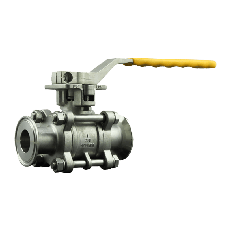
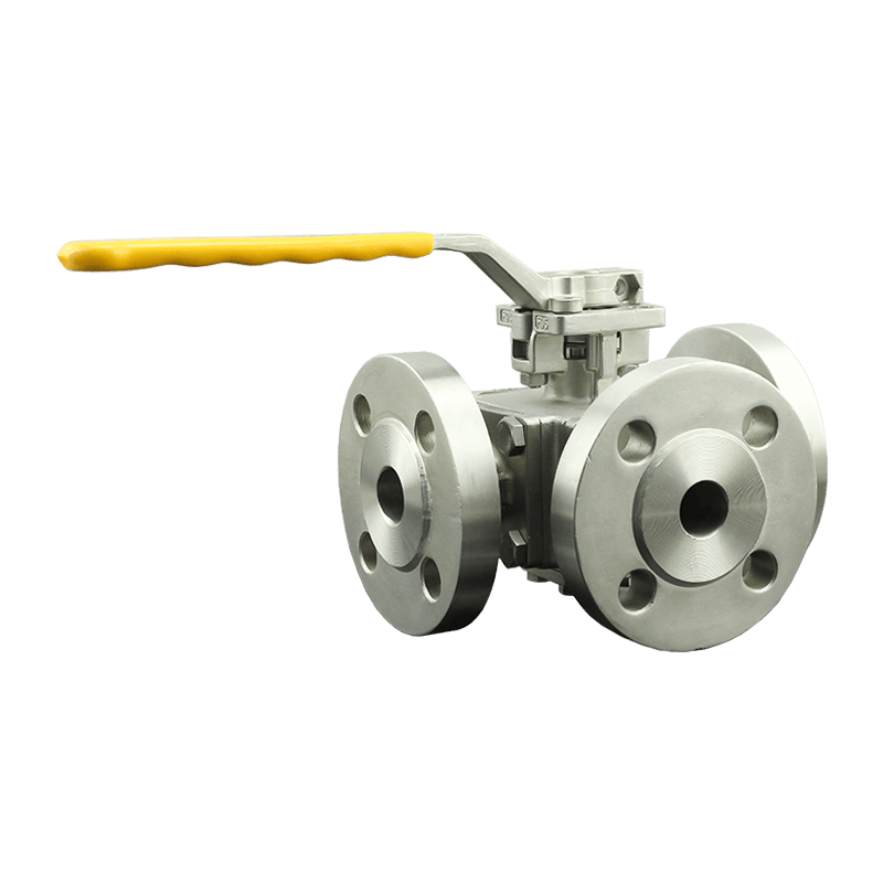
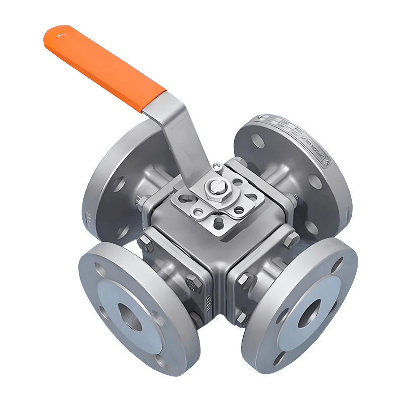
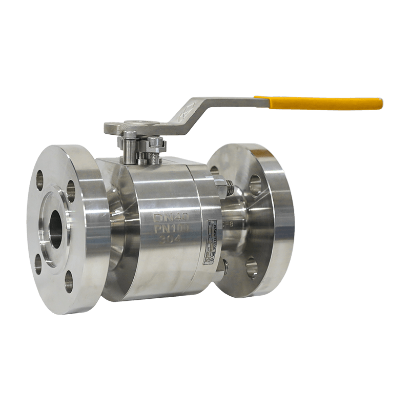
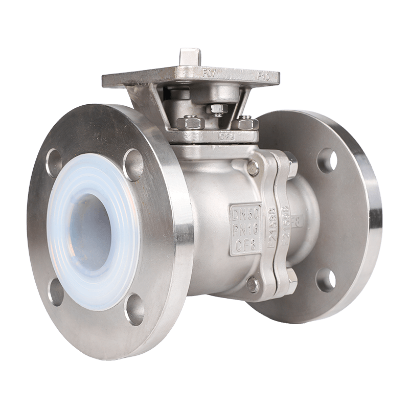
An air valve is only as serviceable as its isolation. Standard practice is to fit a shutoff valve directly beneath the air valve connection so the device can be inspected or replaced without draining the line, and a compact flanged ball valve is the usual choice for this duty.
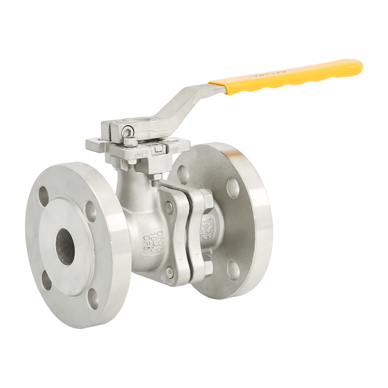 Manual Two-Way Flanged Ball ValveA flanged two-way ball valve with anti-blowout stem and adjustable PTFE packing, offered in stainless and duplex alloys. It is the standard isolation valve installed beneath an air valve so the device can be serviced without draining the line.View Product →
At pump stations, air valves work alongside other protection. Swing check valves on the discharge side stop reverse flow and slam when the pump stops, while the air and vacuum valve covers the vacuum side of the same transient. Specifying the two together, against one surge scenario, is what keeps the station protected as a system.
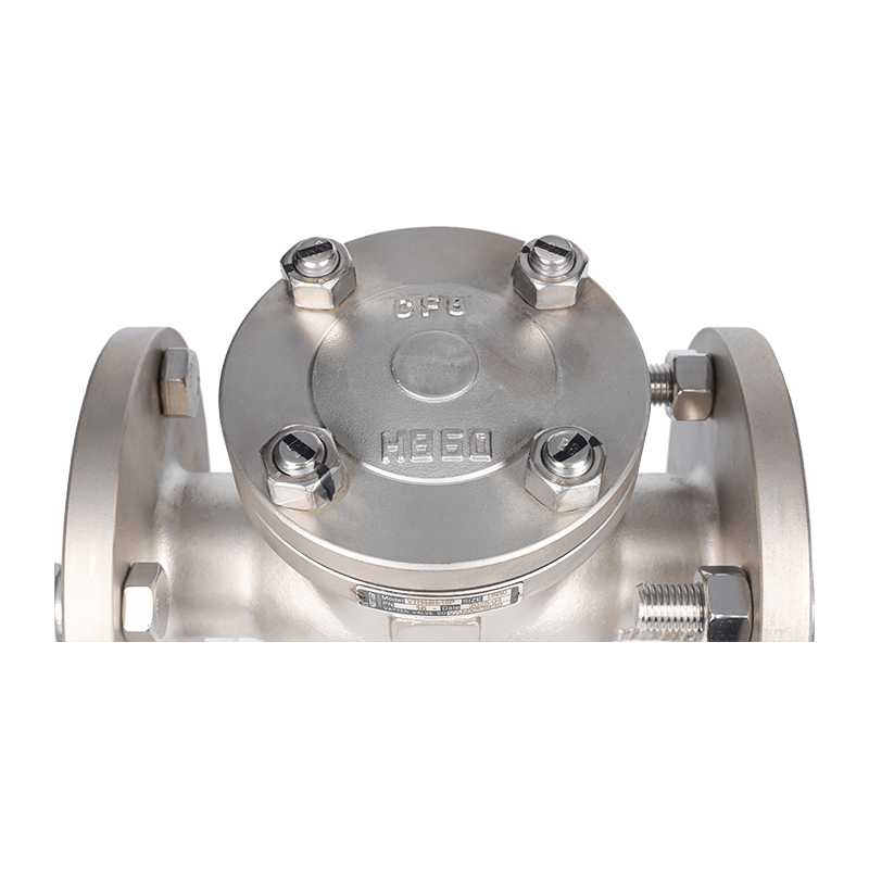 H44H Swing Check ValveAn automatic swing check valve that blocks reverse flow with STL-hardfaced disc and seat sealing. At pump discharge it prevents backflow and slam when the pump stops, complementing air and vacuum valves against the same surge transient.View Product →
Air problems also become visible problems when the line is instrumented. A pressure transmitter at a suspect high point or on the pump discharge records the transient events that air valves are absorbing, turning vague complaints about air in the line into data that justifies the valve layout, or a revised one.
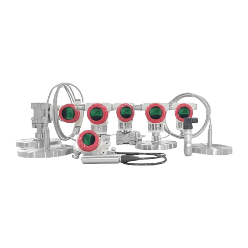 FDP3000 Monocrystalline Silicon Smart TransmitterA smart pressure transmitter with 4-20mA HART output, high long-term stability, and lightning protection. Installed at suspect high points or pump discharge, it records the transient events that air valves absorb, turning air complaints into data.View Product →
A Six-Point Specification Checklist
Before signing off a purchase order, run through six checks:
- Prefer combination valves for critical mains and pump stations.
- Verify air discharge and admission capacities from manufacturer curves at your actual working pressure.
- Match flange standard, pressure class, and materials to the pipeline specification.
- Choose anti-clog designs for wastewater, sludge, or other dirty services.
- Include an isolating valve under every air valve, plus an anti-slam device where surge risk is real.
- Confirm safe access for periodic float and seat inspection.
Air release valves earn their keep quietly. No display, no actuator, no alarm: just a float doing its job through every filling, draining, and pressure transient of the season. Treating them as engineered components rather than pipe fittings is what separates a protected pipeline from one that mysteriously loses capacity each summer. When you also need the surrounding hardware, including isolation ball valves, check valves, control valves, and the pressure instrumentation that makes air problems measurable, sourcing it from a single valve partner keeps pressure classes and materials consistent across the system. Vatten Valve Group supplies these categories for water treatment, chemical, and general process service, with project-level valve supply experience across demanding industries.