 English
 Deutsch
 Indonesia



Content
- 1 What a Differential Pressure Transmitter Measures
- 2 Where the Measurement Earns Its Place
- 3 The Six Datasheet Lines That Decide the Result
- 4 Installation Details That Change the Reading
- 5 Calibration, Zero Checks and Drift
- 6 How the Transmitter Sits Inside the Control Loop
- 7 When a DP Transmitter Is the Wrong Instrument
- 8 What to Confirm Before the Order Goes Out
A level reading that climbs 600 mm after a weekend shutdown is rarely a level problem. The low-pressure impulse line on the differential pressure transmitter is holding condensate that nobody drained, so the instrument keeps reporting a difference that no longer exists.
That is the nature of the device: it measures a difference, not a pressure. Anything that changes either side of the diaphragm, whether a wet leg, a plugged tap, a hot process connection or a manifold valve left half open, appears in the output signal as if it were a real process change.
The conclusion is worth stating before the details. Fix four things first: the span you actually need, the static pressure the body must hold, the wetted materials and fill fluid, and the way the impulse lines are installed. A mid-range transmitter sized and piped correctly will beat a premium unit chosen from a catalogue page.
What a Differential Pressure Transmitter Measures
A differential pressure transmitter has two process ports, marked high (H) and low (L), and it reports H minus L. It has no idea what the absolute pressure is in either line. The output is a continuous signal, usually 4-20 mA, often with HART superimposed, occasionally RS-485 or a fieldbus. On flow duty, square-root extraction is applied either in the transmitter or in the control system, so the signal becomes proportional to flow rather than to pressure difference.
Four numbers describe its behaviour, and they are easy to confuse:
- URL — the upper range limit, the largest span the sensor can be calibrated for.
- Calibrated span — the range you actually use, for example 0-2.5 kPa.
- Turndown — URL divided by the calibrated span.
- Static pressure rating — the line pressure both sides can hold continuously.
The arithmetic matters more than the marketing. A transmitter with ±0.2% of span reference accuracy gives ±5 Pa on a 2.5 kPa span, and ±500 Pa on a 250 kPa span. The same hardware produces one hundred times the absolute error.
Where the Measurement Earns Its Place
Three duties cover most industrial installations.
- Flow: an orifice plate, Venturi or averaging pitot creates a difference that grows with the square of flow. At 25% of maximum flow, only 6.25% of the maximum DP is available, which is why the low end of a DP range is where measurement quality is really spent.
- Level: in a closed or pressurized tank, the difference across a wet leg or a pair of diaphragm seals translates into head. The calculation assumes stable product density; if the density drifts, the level reading drifts with it.
- Condition monitoring: pressure drop across filters, strainers, heat exchangers and coalescers. Here the instrument follows a trend, so repeatability matters more than absolute accuracy.
All three use the same hardware. What separates a dependable installation from a frustrating one is rarely the sensor; it is the sizing decision and the plumbing around it.
The Six Datasheet Lines That Decide the Result
Datasheets are written to look good side by side. These six lines determine whether the loop still works after commissioning.
| Specification | What it decides | Trap to watch |
|---|---|---|
| Calibrated span and turndown | The smallest DP you can resolve | Accuracy quoted as a percentage of URL flatters a wide sensor |
| Static pressure rating | Whether body and seals survive line pressure | A 2 kPa span on a 40 bar line still loads the capsule at 40 bar |
| Reference accuracy | Base error at laboratory conditions | It is a percentage of span, not of reading |
| Wetted materials and fill fluid | Chemical and temperature compatibility | Silicone oil is standard; oxygen and hot service may need another fill |
| Temperature and static pressure effects | Real error during operation | Effects per 28 °C add straight onto the base accuracy |
| Output and protocol | How the signal reaches the controller | Confirm whether square-root extraction is enabled in the transmitter |
Two lines cause most of the trouble. Reference accuracy as a percentage of span means very little when the working span sits at the bottom of a wide sensor. Static pressure effect is the other quiet one: a capsule that handles 40 bar perfectly well still deflects slightly as that pressure moves, and the resulting error is printed a few lines lower in the same document.
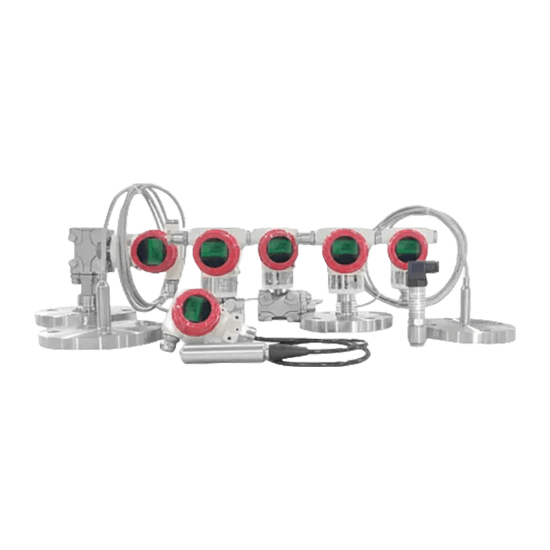 Smart TransmitterSmart Transmitter DescriptionView Product →
Installation Details That Change the Reading
Impulse piping is not plumbing; it is part of the measurement. The rules differ by phase.
- Liquid service: mount the transmitter at or below the taps and slope the lines back to the process at 1:12 or steeper, so gas bubbles find their own way out.
- Gas service: mount above the taps so condensate drains back into the pipe instead of sitting on the diaphragm.
- Steam service: keep both legs filled with condensate using pots or pigtail siphons, and keep them the same length and insulation so the two hydrostatic columns cancel.
- Viscous, crystallizing or hygienic media: replace impulse lines with capillary remote seals, and check the fill fluid temperature limit, which is usually lower than the process limit of the seal.
- Manifolds: a three-valve manifold is the minimum for zeroing; five-valve versions add blow-down. Vent lines away from people and equipment.
On closed tanks, remember zero elevation and suppression. A wet leg adds a fixed head that must be subtracted in the configuration, and if that leg is partly evaporated or refilled, the reading shifts by exactly the height difference.
Calibration, Zero Checks and Drift
Field calibration is simpler than it sounds, provided the sequence is respected.
- Isolate the transmitter and open the equalizing valve so both sides see identical pressure.
- Vent both sides, then perform a zero trim, which on most transmitters is the only adjustment that belongs in the field.
- Pressurize with a calibrated source through all five points, 0 to 100% and back, to expose hysteresis.
- Confirm square-root extraction, damping and alarm settings after the pressure check, never before.
- Record as-found and as-left values; three years of certificates say more about a sensor than any single test.
A realistic drift figure is around ±0.1% of span per year, but ambient swings and a changed line pressure move the reading without any drift at all. Critical loops justify a quarterly check; utility loops can run annually with a spare on the shelf.
How the Transmitter Sits Inside the Control Loop
In a flow control loop the transmitter measures, the controller decides and the control valve acts. The common mistake is buying the three parts separately. A DP measurement on an orifice plate is highly repeatable, but the valve trim must be sized for the same flow range, and the relationship between Cv and Kv values and real flow matters as much as the transmitter's accuracy. That conversion is explained in the Cv and Kv conversion guide.
If a transmitter needs quarterly recalibration and the valve hunts at the same time, look at the loop rather than the instrument. A smart positioner holds the trim where the controller asks and reports travel data that separates a measurement problem from an actuation problem.
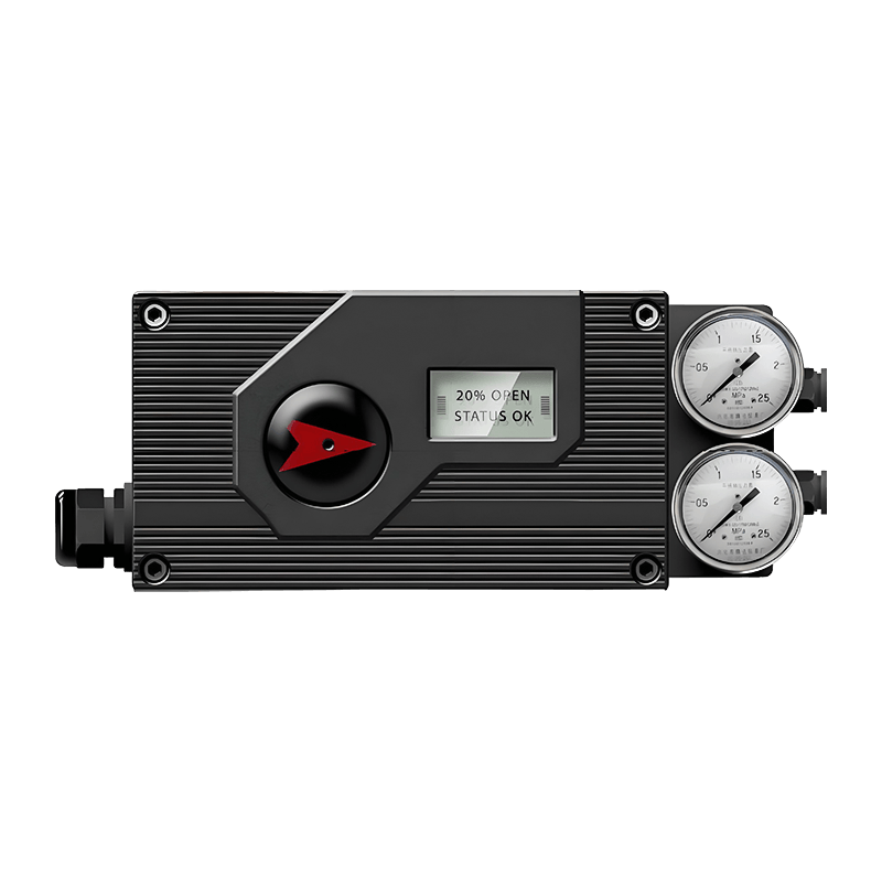 VATTEN Smart Valve PositionerVATTEN Smart Valves Positioner DescriptionView Product →
When a DP Transmitter Is the Wrong Instrument
DP measurement is versatile, but it is not universal. Reach for something else when:
- Level is measured in an open tank and product density changes with batch, temperature or solids content. That error cannot be trimmed out.
- Foam, vapour or a boiling surface disturbs one of the sensing points.
- Flow is clean and conductive, where an electromagnetic flowmeter removes the permanent pressure loss of an orifice altogether.
- The difference itself is tiny, in the low pascal range, such as cleanroom pressure or a nearly clean filter. A dedicated low-range sensor handles that better than a wide capsule turned down to its limit.
Where level is the real objective, a non-contact instrument removes the impulse lines, the fill fluid and the density assumption in one move.
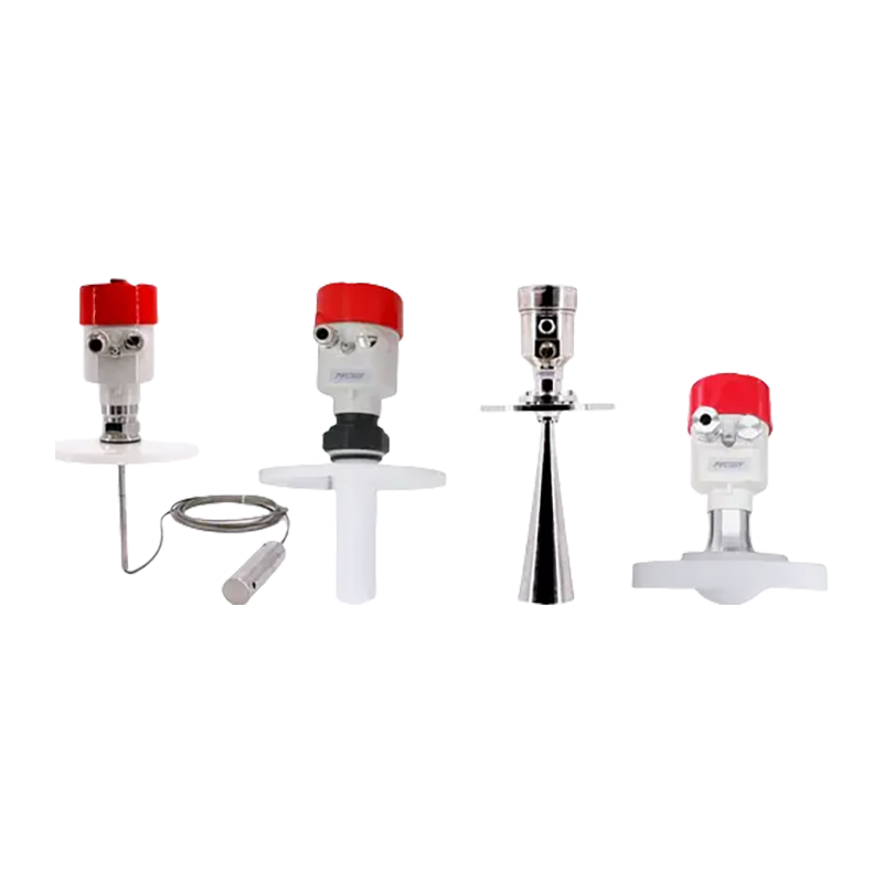 Radar Level MeterRadar Level Meter DescriptionView Product →
What to Confirm Before the Order Goes Out
- Minimum, normal and maximum DP, expressed in the same units the datasheet uses.
- Maximum static pressure on both sides, and whether the process can be blocked in while the transmitter is isolated.
- Process and ambient temperature, since both appear separately in the error budget.
- Wetted parts and fill fluid compatibility, signed off by the process engineer rather than guessed.
- Connection type, mounting orientation and manifold configuration.
- Documentation: calibration certificate, material certificates and the correct hazardous area rating where applicable.
- Seals, fill fluid and one spare transmitter for critical loops.
Most of the cost of a DP measurement is not in the sensor. It sits in the impulse piping, the manifold, the seals, the commissioning time and the recalibration hours over the following decade. Specifying the right span and the right static pressure rating at the start is the cheapest decision available. Vatten Valve Group supplies pressure instruments alongside the valves, actuators, positioners and flow instruments that complete a fluid control loop, so the transmitter, the manifold and the valve that answers to it can be selected against the same process data.