 English
 Deutsch
 Indonesia


Content
- 1 What guided wave radar actually measures
- 2 Where guided wave radar earns its price, and where it fails
- 3 Probe selection decides the result
- 4 Five installation rules that change the reading
- 5 Guided wave radar against free-space radar and ultrasonic
- 6 Closing the loop: from level reading to valve movement
- 7 Commissioning checks and the five faults you will meet
- 8 Guided wave radar questions engineers ask
A 9 m solvent day tank with a running agitator is where most level-measurement arguments start. Free-space radar sees foam and a moving surface; an ultrasonic sensor drowns in solvent vapour. Guided wave radar handles both, but only when the probe reaches past the nozzle and the product dielectric stays above roughly 1.4. Get either detail wrong and the same transmitter will report a flat line for a week.
1 mm to 3 mm typical accuracy on a rigid probe, dielectric constants down to 1.4 with a twin rod, and a top dead zone that usually starts 0.1 m to 0.5 m below the process flange.
What guided wave radar actually measures
Guided wave radar measures level by time-domain reflectometry: a microwave pulse travels down a metal probe, reflects from the product surface, and the round-trip time is converted into a distance.
The arithmetic inside the housing is unremarkable, which is why the technique is trusted in chemical and pharmaceutical service. Propagation speed inside the probe is known, the round-trip time is measured precisely, and the result is halved. What changes from one installation to the next is not the maths but the strength of the reflection, and that is governed almost entirely by the dielectric constant of the product.
Water, acids and aqueous slurries sit above 10 and return a strong echo that tolerates a coated probe. Most hydrocarbons, solvents and condensates sit near 2 and return a weak echo that needs a twin rod or a coaxial probe to stay dependable. Below about 1.4 the reflection is so small that the transmitter spends its day hunting noise.
Where guided wave radar earns its price, and where it fails
Guided wave radar is the better choice when the product foams, when the tank is short or crowded with internals, or when the dielectric is low enough to starve free-space radar. It is the wrong choice when the probe cannot stay clean or when the vessel is tall enough to force a flexible cable.
Strong fit
- Solvent, LPG and condensate service on a twin-rod probe
- Foaming products in mixing and fermentation vessels
- Saturated steam and condensate duties
- Powder silos with heavy dust loading
- Oil and water interface layers on a coaxial probe
Weak fit
- Crystallising media that coat the rod
- Silos beyond about 20 m needing a cable probe
- Products with a dielectric below 1.4
- Viscous media that bridge twin rods
- Tanks where a probe would foul the agitator
Probe selection decides the result
The probe, not the transmitter, decides whether the measurement holds, because geometry sets the minimum dielectric, the usable range and the tolerance to build-up and turbulence.
| Probe type | Typical service | Dielectric floor | Watch out for |
| Single rod | Clean liquids, day tanks, dosing vessels | 1.8 to 2.0 | Coating shifts the zero point |
| Twin rod | Solvents, LPG, low-dielectric liquids | 1.4 | Bridging in sticky products |
| Coaxial | Interface layers, clean low-dielectric products | 1.4 | Narrow gap clogs with slurry |
| Flexible cable | Tall silos, powders and granules | 1.6 | Cable sway and signal loss over 20 m |
| Bypass chamber | Agitated reactors, foaming products | 1.4 | Chamber must be vented and isolated |
Coaxial probes are the safest answer for clean low-dielectric liquids and for interface work, because the pulse is shielded from the vessel wall and the inner rod cannot sway. Twin rods cover most solvents and liquefied gas but bridge easily in sticky products. Flexible cable probes exist for tall silos, where the trade-off is attenuation along the cable and mechanical movement in an agitated vessel.
Five installation rules that change the reading
Most guided wave radar problems are decided before the transmitter is powered up, and they come down to five installation habits.
- Mount clear of the fill stream. A probe sitting in the incoming flow reads turbulence and foam, not level, and the error appears only during transfer.
- Let the probe pass the nozzle. The measurement reference is the tip, so a rod that ends inside a 200 mm nozzle creates a false echo no suppression routine removes cleanly.
- Respect the top dead zone. Configure the upper range value below the blind zone so the current output never carries a reading the instrument cannot verify.
- Ground the vessel and the mounting. Lined and plastic tanks need a reference ground, otherwise the pulse finds a return path through the thread and the echo drifts.
- Use a bypass chamber for agitated or foaming duty. A chamber with isolation valves gives a calm surface and lets you pull the probe without draining the vessel.
Guided wave radar against free-space radar and ultrasonic
Guided wave radar wins on low-dielectric media, foam and cramped vessels; free-space radar wins on very tall silos and on keeping the sensor out of the product; ultrasonic wins on price in clean, short-range open tanks.
| Criterion | Guided wave radar | Free-space radar | Ultrasonic |
| Typical accuracy | 1 to 3 mm | 3 to 10 mm | 0.25 percent of span |
| Foam and vapour | Tolerant | Degrades | Fails |
| Minimum dielectric | 1.4 with twin rod | 1.8 to 2.0 | Not relevant |
| Build-up effect | Direct on reading | Moderate | Severe |
| Wetted parts | Probe in product | None | None |
| Relative cost | Mid | Mid to high | Low |
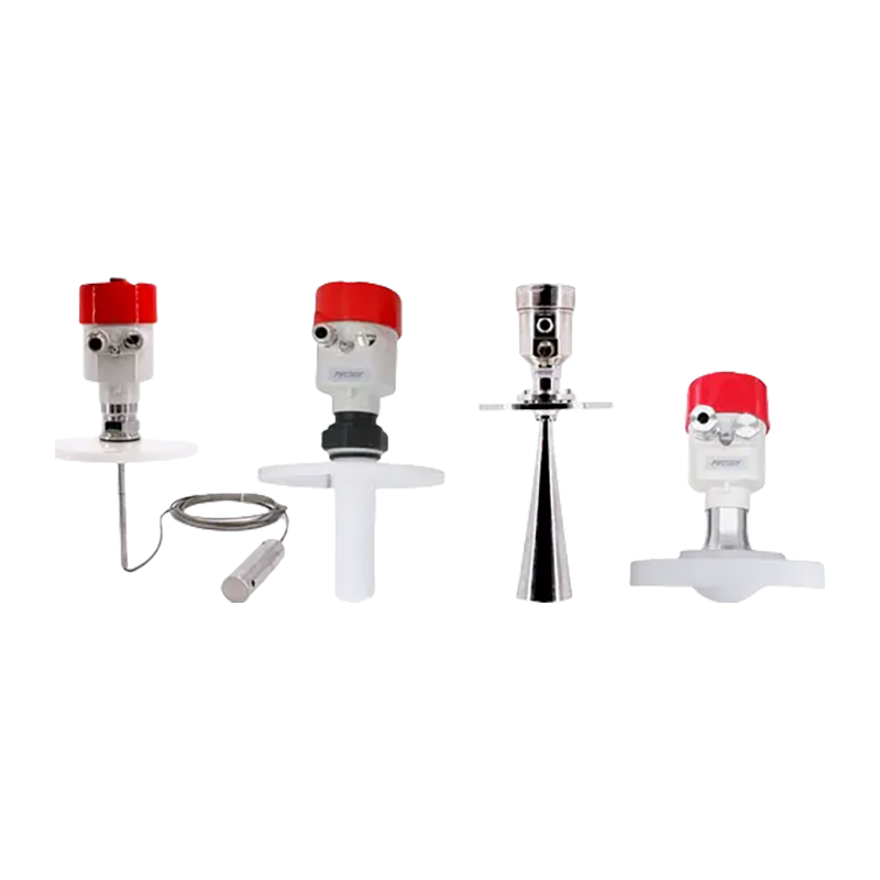 FvLuoky FRL21 Series Radar Level MeterFor level and material measurement in petrochemical, water treatment and chemical service, with millimeter display, multiple frequency options and ±2 mm or ±5 mm accuracy.View Product →
Where the requirement is only a high alarm, a low alarm or a pump cut-out, a simpler float device usually beats both radar options on cost and on maintenance, and it is easier for a shift team to prove during a walkdown.
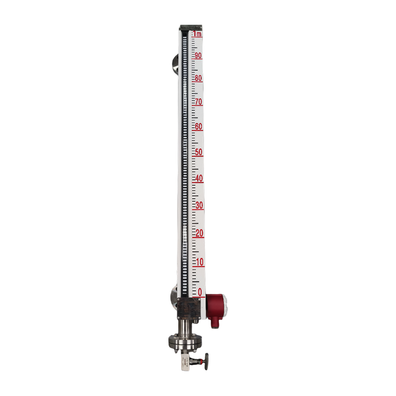 FvLuoky FFL500 Series Magnetic Float Level MeterA simple liquid-level indication and control option for alarm or pump cut-out duties, with LCD display, ±10 mm accuracy and 4–20 mA or switch output.View Product →
Closing the loop: from level reading to valve movement
A level transmitter only reports. The loop closes when that signal reaches a controller and the controller strokes a valve.
On a typical skid the transmitter sends 4-20 mA or Modbus into the PLC, and the controller output drives an electric or pneumatic valve on the outlet line. The architecture is ordinary distributed control: field device, controller, final element. What decides whether the loop behaves is rarely the protocol. It is transmitter damping and valve dead band.
Set damping too high and the loop hunts; set it too low and every ripple on the surface becomes valve movement. A dead band wider than the level tolerance produces a sawtooth trend that maintenance will eventually blame on the radar, even though the instrument is reporting honestly.
On the final element, an electric actuated control valve with a smart positioner gives the loop a repeatable stroke and a feedback signal the historian can trend. When a valve is sticky, the level curve looks identical to an instrument fault and the transmitter gets replaced for nothing.
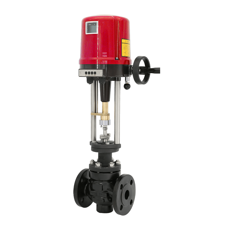 Vatten Electric Smart Control Valve with Intelligent ActuatorElectric actuated control valve with 4–20 mA input/output, linear stroke adjustment and broad body and trim material options for precise final-element control.View Product →
Sizing, trim choice and the common failure modes of the final element are covered in the site's control valve selection guide, which is worth reading before the loop is tuned.
Commissioning checks and the five faults you will meet
Almost every guided wave radar call-out falls into one of five patterns, and each has a known cause and a quick test.
- No echo at low level: probe too short, or the lower range end not configured. Lower the range and watch the echo curve.
- Reading jumps when the agitator starts: probe vibration. Move to a bypass chamber or switch to a coaxial probe.
- Slow drift over weeks: build-up on the probe. Clean it and compare against a manual gauge before touching the electronics.
- Echo lost after a batch change: thicker foam, or a product with a lower dielectric than the original specification.
- Reading pinned near range top: false echo from nozzle, weld or gasket. Run echo suppression with the vessel empty.
Guided wave radar questions engineers ask
How accurate is guided wave radar in real service?
With a rigid probe, a short nozzle and a stable product, 1 mm to 3 mm is realistic. With a flexible cable in a tall silo or a coated probe, expect several times that figure regardless of the datasheet.
Can guided wave radar measure through foam?
Usually yes, provided the foam is not extremely light and deep. The pulse travels inside the probe, so surface foam disturbs the reflection far less than it disturbs a free-space radar beam.
What dielectric constant is too low?
Below about 1.4 the reflection becomes unreliable. Twin rod and coaxial probes extend the working range downward, but a product that low in dielectric is often better measured by a different principle.
Does guided wave radar need a bypass chamber?
Not always. It is strongly recommended for agitated, foaming or high-viscosity service, because a chamber gives a calm measuring surface and allows the probe to be removed without draining the vessel.