 English
 Deutsch
 Indonesia

Control valve vibration refers to the rapid opening and closing of the valve during operation, indicating that the control valve cannot stably maintain an appropriate position to sustain the predetermined proc...
READ MOREWhy Choose Us?
Vatten Valve Group, a globally renowned industrial automation valve enterprise originating from Saarland, Germany, specializes in the research, development, and manufacturing of core products such as automatic control ball valves, butterfly valves, and regulating valves. Leveraging our exceptional technological expertise, we deliver innovative valve solutions and professional technical support to critical industries including energy, chemical, water treatment, pharmaceutical, and food processing.
Self Control Valve Supplier
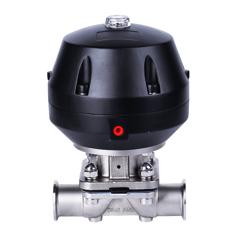
Pneumatic Diaphragm Valves Manufacturers
The pneumatic diaphragm valves produced by VATTEN are widely used in various fields such as water treatment, pharmaceuticals, and chemicals. As an efficient and reliable control device, it can accurately regulate the flow of fluids, meeting the needs of different industries for fluid management.
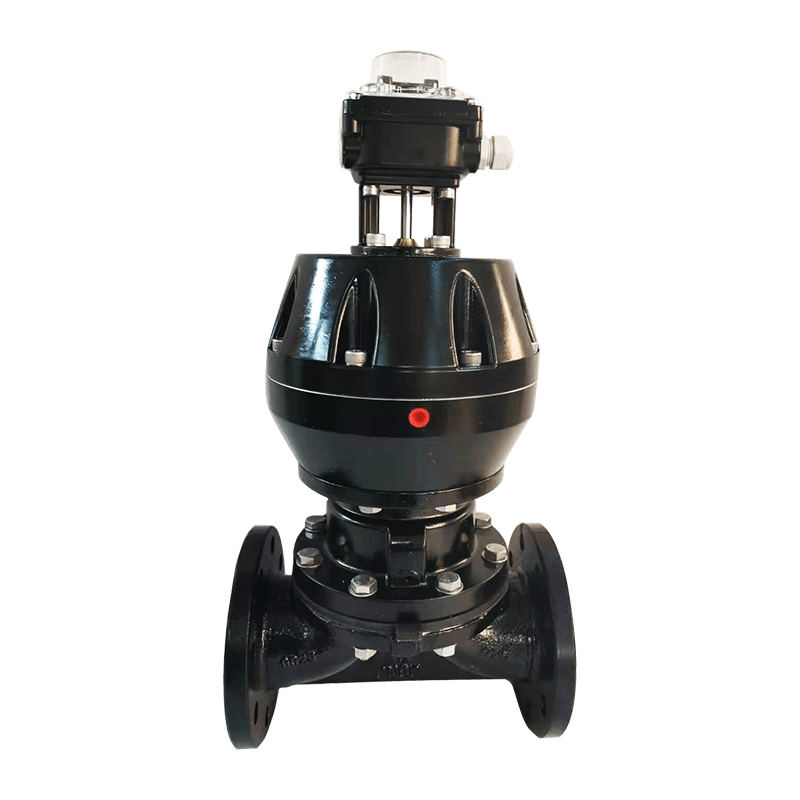
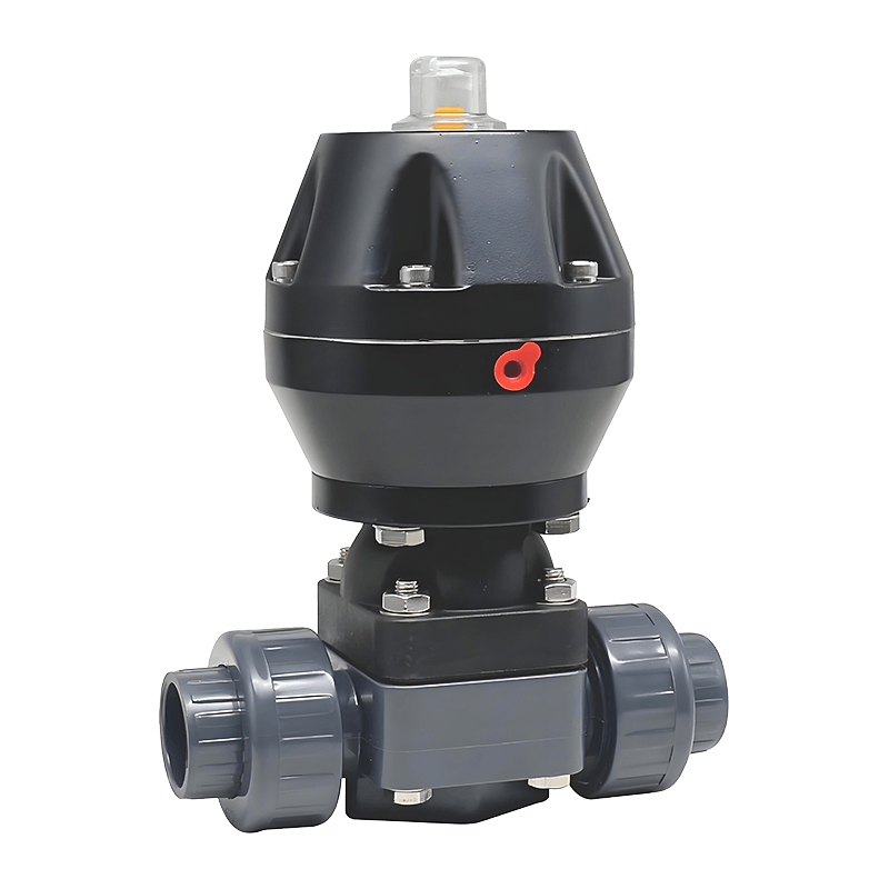
The pneumatic actuator comes in two material options: aluminum alloy and plastic head. The aluminum alloy actuator offers higher corrosion resistance and a longer service life, while the plastic head provides better cost-effectiveness and lighter weight, making it suitable for environments where high corrosion resistance is not required. Users can choose the appropriate material based on their specific needs.
In addition, the internal structure of the pneumatic diaphragm valve can be polished to pharmaceutical-grade standards, which is particularly important in the pharmaceutical industry. The pharmaceutical-grade polishing ensures the smoothness of the valve body, preventing the accumulation of contaminants and ensuring the purity and safety of the fluid. This design is crucial for the production process of pharmaceuticals and complies with strict industry standards.
Message Feedback
About Us
Vatten Valve Group, a globally renowned industrial automation valve enterprise originating from Saarland, Germany, specializes in the research, development, and manufacturing of core products such as automatic control ball valves, butterfly valves, and regulating valves. Leveraging our exceptional technological expertise, we deliver innovative valve solutions and professional technical support to critical industries including energy, chemical, water treatment, pharmaceutical, and food processing.
As Pneumatic Diaphragm Valves Manufacturers and Pneumatic Diaphragm Valves Company, the Group operates four state-of-the-art manufacturing bases strategically located in Shanghai, Tianjin, Lishui, and Jiaxing, China. To better serve international markets, we have established branch offices in key strategic locations including the United Kingdom, Turkey, Belarus, Saudi Arabia, and Indonesia. The establishment of our Indonesian office significantly enhances our service capabilities in the Southeast Asian market, ensuring timely and efficient technical support and services for local partners and clients.
Rooted in the German tradition of precision manufacturing, Vatten Valve maintains its focus on automatic control valves while strictly adhering to international quality standards. Provide Custom Pneumatic Diaphragm Valves. We are committed to continuous innovation, providing customers with superior performance products, professional technical support, and comprehensive fluid control solutions, empowering them to address complex industrial fluid control challenges.
News
-
-
Bottom discharge valves are flow-control devices installed at the lowest point of a vessel, tank, or hopper to allow controlled release of bulk solids, slurries, or liquids by gravity. They are a critical comp...
READ MORE -
Electric Flow Control Valves: Key Answer and Practical Value Electric flow control valves regulate fluid flow automatically using an electric actuator that adjusts valve position based on control signals. They...
READ MORE -
Key Conclusion: Why Check Valves Are Essential in Fluid Systems Check valves are installed to allow fluid to flow in only one direction and automatically prevent reverse flow without manual intervention. Their...
READ MORE
Industry Knowledge
Material selection and media-compatibility guidance
Choosing the correct diaphragm and body materials is a primary operational decision for pneumatic diaphragm valves. Match diaphragm elastomer or thermoplastic to the chemical and thermal profile of the media rather than defaulting to the most common material — improper matches lead to swelling, loss of elasticity, embrittlement, accelerated crack growth, or catastrophic leak paths. For example, EPDM tolerates hot water, steam traces, and many alkaline cleaners but is attacked by mineral oils and many hydrocarbons; PTFE diaphragms withstand aggressive solvents and oxidizers but require careful sealing details because PTFE is less elastic and depends on backup elastomers for leak-tight dynamic sealing.
Diaphragm constructions and failure modes — diagnosis and repair
Understanding how diaphragms fail helps prioritize inspection and spare stocking. Typical failure modes include mechanical abrasion at the stem/plug interface, chemical attack (softening or hardening), thermal cracking from steam sterilization beyond material limits, and fatigue from high-cycle throttling. Inspect diaphragms for localized thinning, small surface cracks radiating from stress points, discoloration (chemical attack indicator), and kettle-like bulging which indicates delamination between reinforcement layers.
Practical on-site checks
- Perform a leak-down test by closing the valve and monitoring downstream pressure decay over a fixed interval; compare to baseline values.
- Visually inspect the diaphragm when cycling is stopped: look for pinch lines near the stem and for separation between reinforcement and elastomer.
- Record cycle counts and correlate with manufacturer’s expected cycle life—this identifies components approaching end-of-life before unplanned failure.
Air supply, FRL sizing and actuator considerations
Reliable pneumatic performance requires a stable, clean, and dry air supply sized for simultaneous actuator demand. Use an FRL (filter–regulator–lubricator) near each valve cluster sized for peak flow; undersized regulators cause slow actuation and partial seating which accelerates wear. Specify the actuator type (single-acting spring-close vs double-acting) based on fail-safe requirements and ensure supply pressure margin: many diaphragm actuators require 4–6 bar full-cycle pressure to achieve rated closing force at the highest process backpressure.
Sizing rule-of-thumb and checks
- Calculate total actuator flow (Nl/min) and size FRL ports to exceed the peak by 25% to prevent pressure drop during simultaneous strokes.
- Where fast cycling is required, use larger diameter pilot lines and minimize fittings to reduce pressure drop and response lag.
Valve sizing, Cv calculation and practical throttling advice
Diaphragm valves are often used both as process isolation and for throttling. For accurate sizing, calculate the valve flow coefficient (Cv) from the required process flow at the operating differential pressure. Use the manufacturer’s Cv curve rather than linearizing, because the flow vs. stem position for diaphragm valves can be highly non-linear. For viscous fluids, correct the calculated Cv for Reynolds effects and consider using a larger valve size to avoid cavitation and seat erosion at partial openings.
Practical throttling tips
- Avoid continuous operation at very low openings — these concentrate velocity on the seat and diaphragm and shorten life.
- If fine control is required, use a positioner and cascade control so the diaphragm valve operates around a locally linear portion of its stroke.
CIP/SIP and sterilization: limits and best practices for hygienic valves
In pharmaceutical and food plants, diaphragm valves must survive Clean-In-Place (CIP) and Steam-In-Place (SIP). Not all diaphragms tolerate repeated autoclave-level steam exposures. PTFE-faced diaphragms with FDA-grade silicone or EPDM backup often work for steam up to specified temperatures, but verify temperature-time ratings from the vendor. Control thermal shock by ramping temperatures and avoid dry-steam bursts which can blister elastomers.
- Validate chemical compatibility of cleaning agents at CIP concentrations and temperatures; alkaline cleaners and strong oxidizers have different attack profiles on elastomers.
- Record the number of SIP cycles and plan diaphragm replacement as a preventive action before warranty limits are reached.
Installation and piping: reducing mechanical stress and improving performance
Install pneumatic diaphragm valves so piping stresses are not transferred to the valve body or actuator. Use short flexible connectors or properly supported pipe that aligns with valve ports; avoid side loads on bolted bonnet joints. Orient valves per manufacturer guidance — many seat and self-drain characteristics depend on flow direction and physical orientation.
Quick checklist for commissioning
- Confirm flow direction stamp matches process piping orientation.
- Pressure-test the assembly at 1.5× operating pressure while monitoring actuator compartment for air ingress.
- Fit silencers or mufflers on exhaust ports in noise-sensitive areas and install non-return valves if backflow could trap diaphragm in an open position.
Spare parts strategy and recommended inventory
Keep a minimal but effective spare parts inventory: diaphragms (two per critical valve type), seat inserts, actuator seals, and fasteners that commonly corrode. For critical services, maintain full actuator rebuild kits and a calibrated positioner or limit-switch module to swap quickly. Track part lot numbers and manufacture dates — elastomer batches can vary and a proactive replacement with the exact spec is safer than substituting similar but untested materials.
Material compatibility quick-reference
| Process Media / Property | EPDM | NBR (Buna-N) | PTFE-faced | Silicone |
| Hot water / steam traces | Good | Fair (limited temperature) | Very good (check backing elastomer) | Good (low mechanical wear) |
| Hydrocarbons / oils | Poor | Good | Excellent | Poor |
| Strong oxidizers (bleach, H₂O₂) | Fair (limited exposure) | Poor | Excellent | Fair |
Troubleshooting quick reference
- If valves chatter or fail to hold pressure: check air supply pressure under load, inspect FRL, verify actuator springs (single-acting) are within spec, and confirm Cv selection for the service.
- If leakage persists after diaphragm replacement: inspect seat insert and body sealing faces for grooves or embedded particles; replace seat inserts and deburr mating surfaces.
- If diaphragm life is short in a throttling service: consider moving to PTFE-faced diaphragms or adding a flow diffuser/upstream orifice to reduce jet impingement on the seat.
CONTACT DETAILS
- Address: Ruko Euro Asia Blok OSB 21B. Boulevard Osaka Street, Salembaran, Kosambi, Tangerang Regency, Banten 15214
- TEL: +62 81181207290
- E-mail: [email protected]
QUICK LINK
PRODUCT
If You Are Interested
In Our Products,
Please Consult Us
Copyright © Vatten Valve Group All Rights Reserved. Pneumatic Diaphragm Valves Manufacturers Pneumatic Diaphragm Valves Company
