 English
 Deutsch
 Indonesia


Content
A process line that keeps drifting from its set point is rarely a controller problem. More often, the culprit is the flow control valve: wrong type, oversized trim, or an actuator that cannot respond fast enough. Flow control valves are the final element in nearly every control loop, and their performance decides whether a plant runs at target or spends shifts correcting oscillations. This guide covers how they work, which types throttle best, how actuation affects precision, and what to check before you buy.
What a Flow Control Valve Does
A flow control valve regulates the flow rate or pressure of a fluid by changing the size of the flow passage in response to a signal. In an automated loop, a flow meter or pressure transmitter sends a measurement to the controller, which compares it with the set point and commands the actuator to move. The valve then holds its position until the process returns to target.
The difference between a flow control valve and a shut-off valve comes down to operating range. A shut-off valve is designed for two positions: fully open and fully closed. A flow control valve must hold stable at dozens of intermediate openings, often under changing pressure, and respond fast enough to prevent overshoot. Internal geometry, trim material, and actuator stiffness therefore matter as much as the body material.
Rangeability is the ratio between the maximum and minimum controllable flow rates. A globe valve typically offers rangeability around 50:1, a V-port ball valve can reach 100:1, and a butterfly valve manages roughly 30:1 depending on the design. If your process must control at 5 percent of maximum flow and still stay on set point, a valve with low rangeability will not do the job.
The Main Flow Control Valve Types
Each valve design has its own flow characteristic, which describes the relationship between valve travel and flow rate. The common options are quick opening, linear, and equal percentage, and the right choice depends on the process. The table below summarizes the most common types used for industrial flow regulation.
| Type | Flow characteristic | Rangeability | Best suited for | Main limitations |
|---|---|---|---|---|
| Globe valve | Linear or equal percentage | About 50:1 | Clean liquids, steam, gases; fine throttling | Higher pressure drop, larger body |
| V-port ball valve | Equal percentage | About 100:1 | Slurries, fibrous fluids, large pipe sizes | Trim must match the media |
| Butterfly valve | Modified linear | About 30:1 | Large diameters, water, air | Lower rangeability, torque peak near 70 degrees |
| Needle valve | Linear | About 20:1 | Low flow rates, instrument lines | Small sizes, limited capacity |
| Diaphragm valve | Linear | About 15:1 | Corrosive media, pharmaceutical and food service | Limited pressure and temperature rating |
Globe valves are the traditional choice for throttling because their seat and plug geometry produces a smooth, predictable flow change. V-port ball valves use a V-shaped notch in the ball to create an equal-percentage characteristic, which makes them useful for slurries and wide rangeability. Butterfly valves are compact and economical in large pipe sizes, but their flow characteristic is less forgiving near the closed position. Needle valves provide precise low-flow control in instrumentation and sampling lines. Diaphragm valves isolate the fluid entirely, which suits corrosive chemicals and hygienic processes.
Manual, Pneumatic, or Electric Actuation
Flow control valves can be adjusted by hand, but in an automated plant they are almost always paired with an actuator. The actuator is what turns a valve into a control element.
Pneumatic Actuation
Pneumatic actuation is the traditional workhorse in process plants. A diaphragm or piston actuator converts compressed air into linear or rotary motion, and a positioner continuously adjusts the valve opening to match the control signal. Pneumatic valves respond quickly, fail safely when air pressure is lost, and suit hazardous areas where electrical equipment would need extra protection. The trade-off is the need for a clean, stable air supply and regular maintenance of the positioner and filter-regulator. For most chemical, water, and slurry services, a pneumatic precise flow control valve with hardened trim covers the majority of applications.
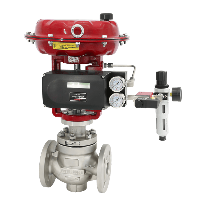 Pneumatic Flow Control ValveThe VATTEN pneumatic...View Product →
Electric Actuation
Electric actuation is increasingly used where precision and digital integration matter more than raw speed. An electric actuator drives the valve with a motor and gear train; a smart positioner reports actual position, diagnostic data, and alarm conditions back to the control room. Electric systems need no air infrastructure and hold a fixed opening very steadily. If you are standardizing on electric drives, an electric smart control valve combines the valve, actuator, and positioner in a single package and is a practical starting point. The decision depends on response time, air availability, maintenance skills, and the plant's control architecture. For a deeper comparison, see our guide on electric flow control valve working principles and selection.
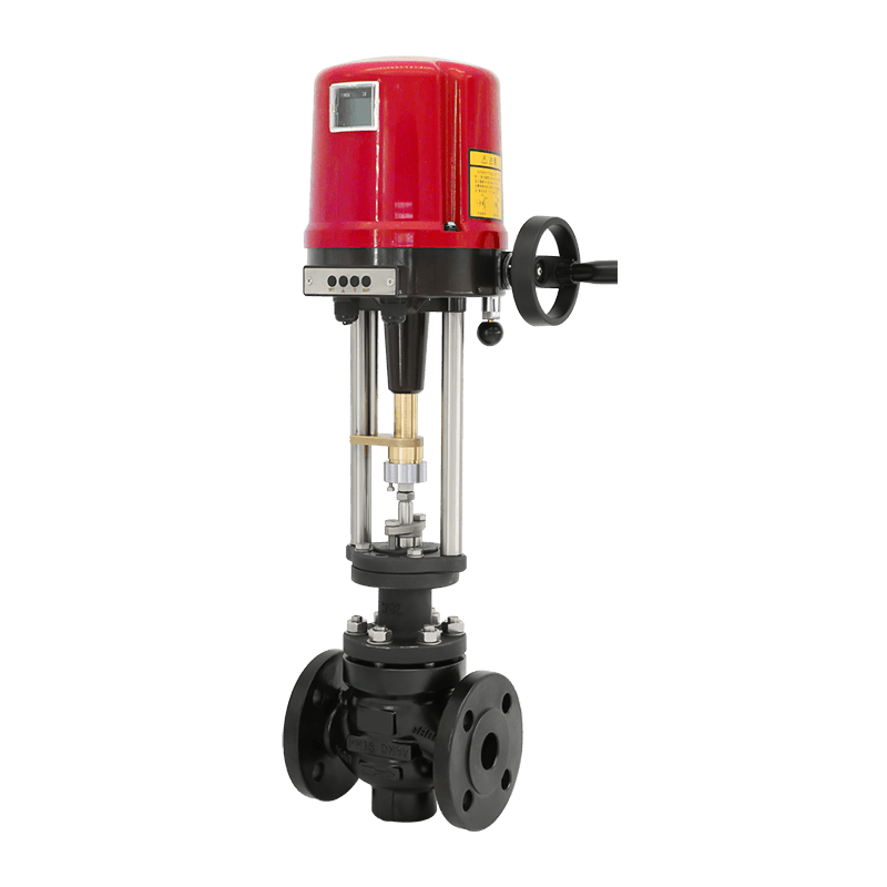 Electric Flow Control ValveThe VATTEN electric ...View Product →
Self-Operated Regulators: Flow Control Without External Power
Not every flow control application has access to compressed air or a reliable electric supply. In remote skids, nitrogen-blanketed tanks, fuel gas lines, and small utility systems, a self-operated regulator uses the process energy itself. A diaphragm senses the controlled pressure or flow and moves the valve plug directly, without a positioner or external power.
A self-operated pressure and flow control valve is a simple, low-maintenance option for set-and-forget duties. It is slower and less accurate than a fully instrumented loop, but for tank blanketing, low-pressure gas lines, and auxiliary cooling circuits, it is often the most reliable and economical choice.
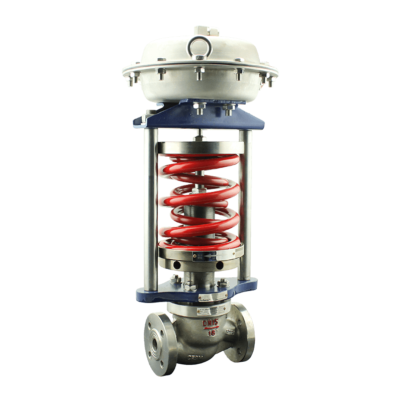 Self-Actuated RegulatorThe self-standing co...View Product →
Sizing and Selection Considerations
Most flow control valve problems come from incorrect sizing. An oversized valve operates near the closed position, where the flow curve is steep and unstable; a small change in travel produces a large change in flow, and the controller oscillates. An undersized valve never reaches the required flow rate, and the loop saturates.
Sizing starts with the flow coefficient, expressed as Cv in US units or Kv in metric units. Cv is the number of US gallons of water per minute that pass through the valve at a pressure drop of one pound per square inch. To select a valve, you need the maximum and minimum expected flow rates, the corresponding pressure drops, and the specific gravity of the fluid. For liquids, the standard ISA-75.01 equation includes corrections for choking and laminar flow; for gases and steam, compressibility and expansion factors must be added.
Beyond the math, remember these points:
- Flow characteristic: equal percentage is usually a safe choice when the pressure drop varies, because it provides finer control at low openings.
- Cavitation and flashing: when downstream pressure falls below vapor pressure, cavitation can erode the trim and create noise, so hardened trim or an anti-cavitation design may be required.
- Leakage class: if the valve must isolate the line during shutdown, specify a higher shut-off class such as Class V or VI.
- Fail-safe position: decide whether the valve must close, open, or hold its position when the air or power supply is lost.
The practical impact of drive types and failure modes is covered in more depth in our guide to flow control valve selection, drive types, sizing, and failure.
A Practical Selection Checklist
Before you order a flow control valve, write down the following:
- Process fluid and its state: liquid, gas, steam, or slurry.
- Maximum, normal, and minimum flow rates.
- Upstream and downstream pressures at each flow condition.
- Temperature range and fluid properties such as viscosity and vapor pressure.
- Required rangeability and control accuracy.
- Actuation method: manual, pneumatic, electric, or self-operated.
- Fail-safe position and response time requirements.
- Materials of construction compatible with the media.
- Leakage class and isolation requirements.
- Additional risks: abrasive particles, corrosion, cavitation, or noise limits.
If the medium contains solids, choose a valve with a hardened metal seat or ceramic lining. If the fluid is highly corrosive, a fully lined design is often more cost-effective than an exotic alloy. If the installation is in a hazardous area, confirm that the actuator and positioner carry the appropriate explosion-proof certification.
The final step is validation. Ask the supplier for flow and rangeability data at your operating conditions, and check that the positioner and actuator match the control signal and response requirements. A valve that looks correct on paper can still fail if paired with an oversized actuator, an underpowered positioner, or a control system that demands more speed than the valve can deliver.
Flow control valve selection is not a one-size-fits-all exercise. The right choice balances the valve type, flow characteristic, actuator, and size against the real conditions of your process. Define the operating envelope, confirm the rangeability, and match the actuation to the plant's control philosophy. When those decisions line up, the valve does what the controller asks and the process stays where it should.