 English
 Deutsch
 Indonesia

Control valve vibration refers to the rapid opening and closing of the valve during operation, indicating that the control valve cannot stably maintain an appropriate position to sustain the predetermined proc...
READ MOREWhy Choose Us?
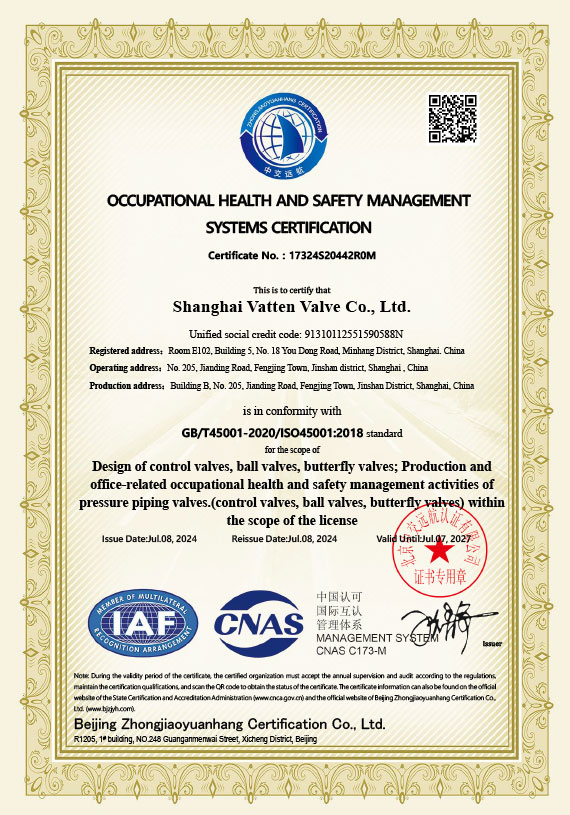
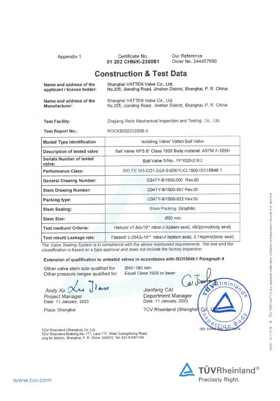
Vatten Valve Group, a globally renowned industrial automation valve enterprise originating from Saarland, Germany, specializes in the research, development, and manufacturing of core products such as automatic control ball valves, butterfly valves, and regulating valves. Leveraging our exceptional technological expertise, we deliver innovative valve solutions and professional technical support to critical industries including energy, chemical, water treatment, pharmaceutical, and food processing.
Self Control Valve Supplier
Valve Limit Switch Manufacturers
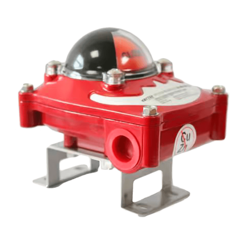
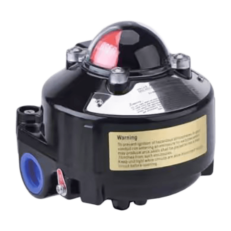
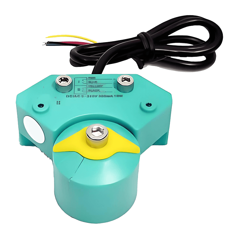
The VATTEN limit switch is an essential feedback device in valve control systems, playing a crucial role in monitoring the valve's open and close status. The switch is equipped with high-quality contact elements from Honeywell and P+F, ensuring accuracy and reliability. Whether in high-frequency operation environments or applications requiring precise control, the limit switch provides timely and accurate feedback, preventing issues caused by poor contact or operational errors.
In addition, the VATTEN limit switch offers an ExdIICT6 explosion-proof rating option, making it suitable for use in hazardous environments. This explosion-proof rating allows the switch to operate safely in explosive gas atmospheres, ensuring the protection of both equipment and personnel. This design consideration makes the VATTEN limit switch even more reliable in industries like petroleum and chemicals, where it can withstand harsh operational conditions.
Combining high-quality components, precise feedback functionality, and a robust explosion-proof design, the VATTEN limit switch is widely used in various industrial automation devices and valve control systems.
Message Feedback
About Us
Vatten Valve Group, a globally renowned industrial automation valve enterprise originating from Saarland, Germany, specializes in the research, development, and manufacturing of core products such as automatic control ball valves, butterfly valves, and regulating valves. Leveraging our exceptional technological expertise, we deliver innovative valve solutions and professional technical support to critical industries including energy, chemical, water treatment, pharmaceutical, and food processing.
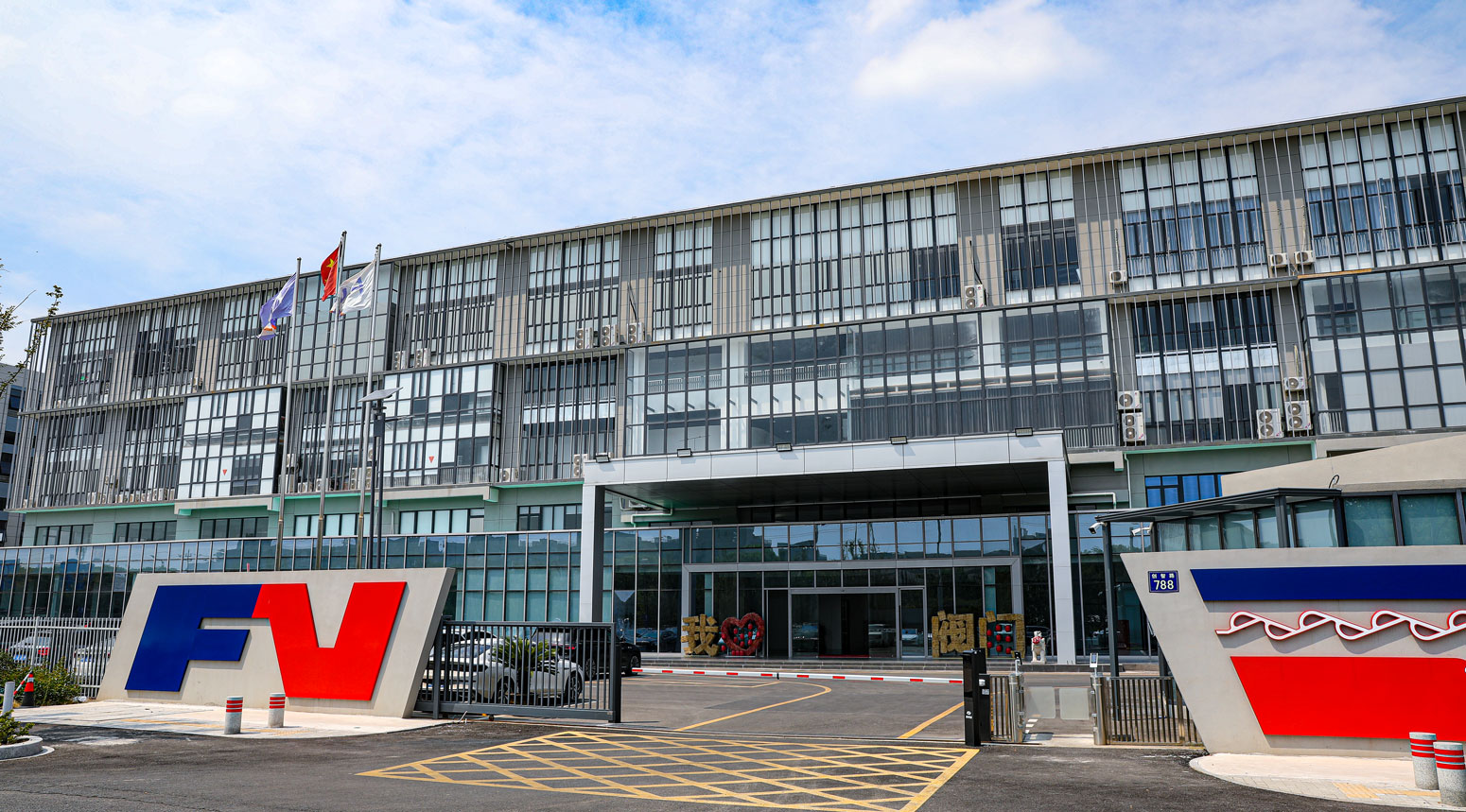
As Valve Limit Switch Manufacturers and Valve Limit Switch Company, the Group operates four state-of-the-art manufacturing bases strategically located in Shanghai, Tianjin, Lishui, and Jiaxing, China. To better serve international markets, we have established branch offices in key strategic locations including the United Kingdom, Turkey, Belarus, Saudi Arabia, and Indonesia. The establishment of our Indonesian office significantly enhances our service capabilities in the Southeast Asian market, ensuring timely and efficient technical support and services for local partners and clients.
Rooted in the German tradition of precision manufacturing, Vatten Valve maintains its focus on automatic control valves while strictly adhering to international quality standards. Provide Custom Valve Limit Switch. We are committed to continuous innovation, providing customers with superior performance products, professional technical support, and comprehensive fluid control solutions, empowering them to address complex industrial fluid control challenges.
News
-
-
Bottom discharge valves are flow-control devices installed at the lowest point of a vessel, tank, or hopper to allow controlled release of bulk solids, slurries, or liquids by gravity. They are a critical comp...
READ MORE -
Electric Flow Control Valves: Key Answer and Practical Value Electric flow control valves regulate fluid flow automatically using an electric actuator that adjusts valve position based on control signals. They...
READ MORE -
Key Conclusion: Why Check Valves Are Essential in Fluid Systems Check valves are installed to allow fluid to flow in only one direction and automatically prevent reverse flow without manual intervention. Their...
READ MORE
Industry Knowledge
Optimizing Mechanical Mounting and Actuator Coupling for Accurate Feedback
Mechanical installation errors are a leading cause of false feedback from valve limit switches. For high-precision applications, pay attention to shaft coupling alignment, actuator travel stops, and backlash elimination. Use rigid coupling hardware and torque-checked fasteners to prevent micro-movements that translate into contact chatter. If the valve actuator uses cams or levers, specify hardened cam faces and hardened follower surfaces to maintain repeatable cam profiles over millions of cycles.
Practical mounting checks
- Verify shaft concentricity with a dial indicator; allowable runout should be within manufacturer tolerance for repeatable switching.
- Lock actuator mechanical stops and record end positions; document mechanical end-of-travel to correlate with electrical feedback.
- Use anti-rotation brackets for limit switch housings in vibrating installations.
Contact Technologies and Signal Integrity: Honeywell vs P+F Elements
Choosing contact elements affects contact resistance, bounce characteristics, and service lifetime. Honeywell mechanical microswitches often provide robust metal alloy contacts with predictable bounce and well-documented electrical life curves. P+F (Pepperl+Fuchs) offers both mechanical and electronic switching technologies (including NAMUR and solid-state outputs) with lower contact wear and better EMI immunity in electrically noisy plants. For high-frequency valve actuation, consider hybrid approaches: mechanical contacts for proven safety interlocks combined with solid-state sensors for fast sampling and diagnostics.
| Feature | Honeywell contact modules | P+F modules / solid-state |
| Electrical life (typ.) | High, with defined cycles at rated load | Very high for solid-state; mechanical variants similar to Honeywell |
| Contact bounce | Observable; requires debounce in control logic | Lower (solid-state) or comparable (mechanical) |
| EMC/EMI robustness | Good with shielding and filtering | Superior for electronic outputs |
Electrical Interface, Debounce and Diagnostics for Reliable Position Sensing
Accurate position feedback requires more than a clean mechanical switch. Implement hardware and software debounce, use supervised circuits, and monitor contact resistance trends. Measure contact resistance during commissioning and log changes over time—an increasing trend often precedes contact failure. For safety-critical valves, choose force-guided contacts or dual-channel supervised loops so the PLC/RTU can detect contact discrepancies in real time.
Recommended electrical practices
- Use RC or digital debounce tuned to the shortest expected mechanical bounce window to avoid false transitions without masking real fast events.
- Implement contact supervision (end-to-end resistance checks) to detect wiring or contact degradation.
- Log state-change timestamps to detect intermittent faults correlated with vibration or temperature cycles.
Explosion-Proof Design Considerations (ExdIICT6) in Flammable Atmospheres
Selecting limit switches with ExdIICT6 certification requires attention to conduit entries, cable glands, and temperature class limits. The Exd enclosure prevents ignition sources from propagating to the gas atmosphere; however, installation workmanship (correct sealing compound, certified glands, and torque settings) is equally important to preserve the rating. Also ensure that the ambient temperature and expected surface temperatures of the switch under electrical load remain below the T6 limit.
Field verification checklist for explosion-proof installs
- Verify certificate matches intended gas group and temperature class (Ex d II C T6).
- Use certified flamepath-capable cable glands and apply anti-seize per manufacturer guidance.
- Record enclosure torque values and gland sealing method in commissioning report.
Maintenance, Verification and Life-Cycle Management for High-Frequency Operations
High-frequency valve cycling shortens the life of mechanical contacts. Create a maintenance schedule based on actual cycles rather than calendar time. Use simple counters or event logging to trigger inspections at defined cycle counts. During inspection, check contact surface condition, spring tensions, lubrication of mechanical linkages, and housing ingress seals. Replace contact modules before electrical characteristics drift beyond specified limits.
| Action | Trigger | Acceptance / Follow-up |
| Contact resistance measurement | Every 50k cycles or annually | If > specified ΔΩ, replace module and retest |
| Mechanical play inspection | After harsh events or vibration alarm | Tighten/replace linkages, document torque |
Integration Strategies with DCS/PLC and Redundancy Architectures
For reliable plant control, tie limit switch feedback into both control and safety systems where appropriate. Use voting logic (2-out-of-3) or dual-channel supervised feedback for safety instrumented functions. When retrofitting older systems, add an isolated solid-state sensor channel in parallel with the mechanical contact to provide high-speed diagnostics without altering safety logic. Ensure wiring separation between power, high-current loads, and sensing circuits to reduce interference.
Wiring and logic recommendations
- Route sensor cables in dedicated trays and use screened cable for long runs; terminate screens at one end.
- Implement plausibility checks in PLC (e.g., check that 'open' and 'closed' are not simultaneously active).
- For SIL-capable systems, document architecture and perform failure mode analysis that includes limit switch failure modes.
Environmental Protection: IP Ratings, Temperature Compensation and Vibration Hardening
Select a valve limit switch with an IP rating that matches increased exposure—IP66/67 for washdown or wet locations; higher for immersion. For installations with wide temperature swings, verify that internal materials (seal compounds, lubricants, plastics) are rated across the expected range to prevent seal hardening or contraction that could alter actuation force. Use vibration-damped mounts or potting for electronics in high-vibration zones to preserve calibration and prevent intermittent contacts.
- Validate declared IP rating through site-relevant tests: spray, condensation, and salt fog when applicable.
- Specify temperature-stable lubricants and confirm switch component thermal rating exceeds ambient extremes.
CONTACT DETAILS
- Address: Ruko Euro Asia Blok OSB 21B. Boulevard Osaka Street, Salembaran, Kosambi, Tangerang Regency, Banten 15214
- TEL: +62 81181207290
- E-mail: [email protected]
QUICK LINK
PRODUCT
If You Are Interested
In Our Products,
Please Consult Us
Copyright © Vatten Valve Group All Rights Reserved. Valve Limit Switch Manufacturers Valve Limit Switch Company
