 English
 Deutsch
 Indonesia



Content
A safety relief valve is the last mechanical barrier between a pressure vessel and its design limit. It opens at a preset pressure, discharges enough fluid to stop the pressure climbing, and closes again on its own. Orifice size, spring range, trim material and discharge piping all exist to make that one action repeatable for twenty years.
Take a 10 bar set pressure on a PN16 line. The valve normally starts to crack within a few percent of set, reaches full lift slightly above it, and reseats at around 90 percent. If a downstream block valve is closed and a positive displacement pump keeps running, that narrow band is the entire margin. Size it badly and it chatters, hammers its seat, and relieves far less than the nameplate promises.
Definition: a safety relief valve is an automatic, pressure actuated device that discharges the protected medium to a safe location so internal pressure never exceeds a specified limit, then re-closes without manual intervention.
What a Safety Relief Valve Actually Does
A safety relief valve protects equipment by opening automatically at a preset pressure, discharging the contained medium, and closing again once pressure has fallen back to a safe level. Nothing in the protection loop depends on an operator being awake, which is why the device is classed as the final layer of overpressure protection.
Three terms circulate on datasheets, and the difference shows in how the disc lifts:
- Safety valve: compressible service such as steam, air or gas, with pop action and rapid full lift.
- Relief valve: liquid service, where lift rises proportionally with overpressure and there is no audible pop.
- Safety relief valve: the combined term, since the same body can be trimmed for either duty.
Four pressures define field behaviour, and all four belong on the purchase specification:
- Set pressure: the nameplate value at which the valve begins to open.
- Overpressure: the rise above set needed for full lift, generally 10 percent in gas service.
- Blowdown: the fall below set at which the disc reseats, typically 7 to 10 percent.
- Back pressure: pressure in the discharge header, which pushes on the disc and changes behaviour if it is not compensated.
Spring-Loaded, Pilot-Operated and Self-Actuated
For steam, gas and clean liquid duties between roughly 0.5 and 40 bar, a direct spring-loaded valve is the default choice because it needs no air supply, no power and no controller, and its failure mode is open. The other two families win only when a specific condition rules the spring design out.
Direct spring-loaded
Coil spring opposes process pressure. Works from vacuum to several hundred bar, tolerates dirty media, easy to verify with a lifting lever. Set pressure shifts if back pressure varies, so balanced bellows are needed on a long common header.
Pilot-operated
A small pilot senses pressure and unloads the dome above the main disc. Tighter set point, higher capacity through the same orifice, and far less sensitivity to back pressure. The pilot needs clean, dry media and is harder to prove in place.
Self-actuated and vacuum
Not a substitute for a certified relief device on a pressure vessel, but the right tool for tank blanketing, nitrogen sealing and vacuum protection. Selection details sit in this vacuum relief valve selection guide.
Where the decision is really made:
- Capacity per orifice size, since a pilot design passes noticeably more flow through the same inlet.
- Back pressure above 10 percent of set, which forces bellows trim or a pilot-operated body.
- Media quality, because crystallising or polymerising fluid blocks a pilot passage within weeks.
- How often the set point is changed, since a pilot is adjusted on the dome rather than by re-shimming a spring.
Sizing and Set Pressure: The Numbers Behind the Nameplate
Sizing is governed by the worst credible relief case, not by the line size. Calculate the required mass flow for blocked outlet, control valve failure, thermal expansion and external fire, then select the smallest standard orifice that covers the largest of those cases.
| Parameter | Typical target | Why it matters |
| Set pressure | At or below vessel MAWP | Any margin lost here cannot be recovered by a larger orifice |
| Blowdown | 7 to 10 percent of set | Too tight and the disc chatters, too wide and product is lost every cycle |
| Inlet pressure loss | Under 3 percent of set | A starved inlet causes chatter and premature seat damage |
| Built-up back pressure | Under 10 percent for conventional bodies | Above that, use bellows or a pilot-operated design |
| Discharge pipe velocity | Below the sonic limit of the pipe | Oversized tailpipes vibrate and fatigue the outlet flange |
Installation Details That Decide Whether It Works
Most early failures are installation problems rather than valve defects. The valve needs a short, unrestricted path to the equipment it protects and a discharge route it can genuinely flow into.
- Mount the valve vertically with the spindle upright, on the highest point of the vessel and above the liquid and foam line.
- Never place a shut-off valve between the vessel and the inlet unless it is a changeover arrangement with interlocks and a documented procedure.
- Keep the inlet short and generous, with total pressure loss below 3 percent of set pressure at rated flow.
- Size the tailpipe at least equal to the outlet, support it independently, slope it to a drain, and avoid any water pocket that can freeze or corrode.
- Leave the lifting lever accessible from the walkway and record on the datasheet whether the bonnet is open or closed and whether a lever is fitted.
Testing, Maintenance and the Failures We See Most
A valve that passes a bench test can still fail within a month if the surrounding system works against it, so the service review matters as much as the test certificate.
Stays reliable
- Orifice matched to the calculated relief load, not oversized
- Balanced bellows where the header pressure floats
- Set pressure stamped on a stainless tag at the valve
- Gauge used for the bench test calibrated within twelve months
- Pop test done at temperature, not only cold
Fails early
- Disc lapped every shutdown until the seat geometry is lost
- Pilot installed on dirty or wet gas
- Tailpipe smaller than the outlet
- Set pressure raised in the field without a re-rate check
- No drain, so the outlet fills with condensate
Set the test interval from duty rather than habit. Clean gas and steam service usually justifies an annual bench test, aggressive chemical duty is better at six months, and a valve that has already lifted on process should be inspected before the next campaign regardless of the calendar.
Matching the Valve to the Line
Three spring-loaded configurations cover most utility duties: steam headers, compressed air receivers, water lines and small chemical transfers.
Ordering note: set pressure, fluid and phase, required capacity in kg per hour, connection standard, body and trim material, and whether a closed bonnet or lifting lever is required must all appear on the datasheet. A valve ordered on set pressure alone is a valve that will be re-ordered.
The closed full-lift design with an enclosed bonnet suits steam and gas service where the discharge must be piped away from the operating area.
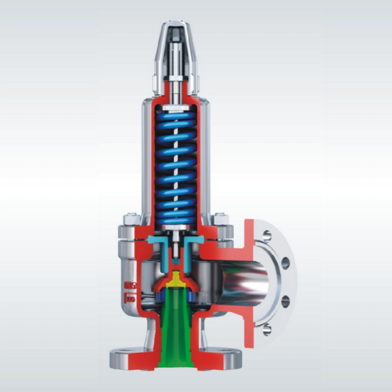 A42Y-C/P/R Closed Full-Lift Spring Safety ValveClosed full-lift safety valve for air, petroleum gas, liquids and corrosive media, with PN 16–100 and DN 20–400 options for industrial pipelines.View Product →
For small receivers, compressor packages and manifold outlets, the male-thread full-lift version with a lifting spanner allows a manual pop test without breaking the joint.
 A28H/Y Male-Thread Full-Lift Safety Valve with SpannerMale-thread spring full-lift safety valve with spanner for air, vapour, water and N2-H2 mixed gas, available in DN 15–65 for small receivers and compressor packages.View Product →
Low-lift valves open proportionally instead of popping, which makes them a better fit for thermal expansion in small liquid volumes, water heaters and low-capacity liquid loops.
 A21H/W/F/Y/W Low-Lift Male-Thread Spring Safety ValveLow-lift male-thread safety valve for air, ammonia, petroleum, corrosive media and liquefied gas, with DN 15–25 sizes for small liquid-volume and water-heater applications.View Product →
FAQ
Short answers to the questions that come up most often during specification and inspection.
What is the difference between a safety valve and a relief valve?
A safety valve is used on compressible fluids and opens with a rapid pop action, while a relief valve handles liquids and lifts in proportion to overpressure. The combined term safety relief valve covers both, because the difference is in the trim and the disc geometry, not in the body casting.
Can a safety relief valve be installed horizontally?
Normally no. The spindle must stay vertical so the spring and disc load remain concentric; a tilted valve loses set pressure accuracy and wears the guide. A few pilot-operated designs permit other orientations, but only with written confirmation from the manufacturer.
Why does my relief valve chatter?
Chatter almost always comes from an inlet that is too restrictive, a valve grossly oversized for the actual relief load, or built-up back pressure above the body's rating. Fix the piping and the orifice first; replacing the spring rarely solves it.
How often should a safety relief valve be tested?
Annual bench testing is the common baseline for steam and clean gas, six months for aggressive or fouling media, and immediately after any unplanned lift. Local codes and insurance requirements override these intervals whenever they are stricter.
Bottom line: choose the valve family from the media and the back pressure, size the orifice from the worst relief case, and protect the installation with a short inlet and a properly supported tailpipe. Those three decisions account for more reliable overpressure protection than any single component upgrade.